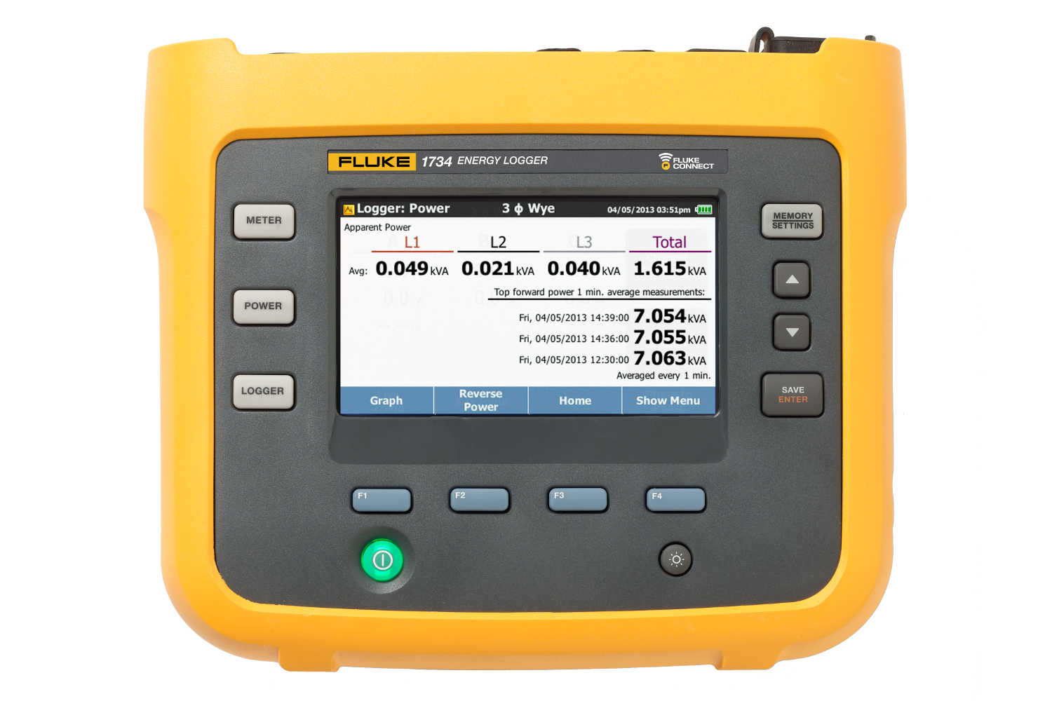
Is XW acting as AC to DC battery charger, so current delivered comes from rectified sine wave, drops to zero ever 1/120th of a second?
vs. DC charge controller delivering constant current from HF PWM through an inductor?
There may be some differences in how BMS measures and reacts to current & voltage. Would have expected better behavior with DC source, but maybe peaks from pulsed current cause it to recognize higher state of charge.
However, does BMS have anything to do with charging behavior (closed loop), or is it just reporting? Do the AC and DC chargers each independently recognize need to go to float based on voltage they see? If each has separate wires to battery, they see voltage at terminals plus IR drop of their own current.
Yes. The DC charge controller is putting out a pretty clean constant DC while the XW-Pro has a lot of 120 Hz current ripple following the AC wave. I thought like you that if anything the BMS would have a better time with the clean DC. The current readout is much more stable, only changing a few tenths of an amps as the MPPT does it's searching. When the XW is charging, it bounces a few amps.
When the XW was my only charge source, I had the CC charge go to 57 volts. It would drop to absorb (constant voltage) mode and the current would ramp down and shut off after 15 minutes. Then the system would sit idle for up to an hour before the Enphase solar production fell to where it would start using battery power.
Now with the added DC charging, the XW is now programmed to go into Absorb CV mode at 56.7 volts. It still makes the obvious transition to CV and the current falls off in about 10 minutes now, because the DC charge controller is still supplying current. On many days, this was happening as early as 11:30 am to noon. So the DC charge controller was still pushing 24 amps into the battery bank. The JK-BMS is only on half of my battery bank. The other half has a pair of dumb Daly BMSs. So when the XW drops to standby, the JK-BMS is showing 12 amps of charge current still. The other 12 amps is going into the Dalys.
Looking at the graph from yesterday, when it was very sunny, the XW absorb phase only lasted about 6 minutes. When the DC charge controller pulls the voltage a little higher, the XW shuts off charge current, as it should in CV mode. On that day, the voltage kept climbing for 4 more hours. At that point, the batteries did reach the DC charge controllers CV set point. They call it "Boost" mode. It is CV at 58 volts now, but it is measuring a the charge controller terminals, AND it reads about 0.2 volts high. So the true battery voltage at this point was 57.8 volts. The XW reports the voltage as staying dead flat from 3:30 to 7 pm. That is 3.5 hours of very little battery current, but it still didn't trigger the reset. The XW battery graph shows the voltage at 57.86 from 4:23 pm to 7:03 pm. That should trigger the BMS to see it as a full battery.
The sun was going down and at 5:51 pm, the Enphase panels were no longer making enough to completely cover all of the loads in the house. So my controller did command the XW to start exporting a tiny bit of power. At 6 pm, the power from the battery bank was up to 243 watts. But that is probably pretty close to what the Charge controller was putting into the batteries, so the true battery bank current was likely very close to zero. But by 7 pm, with the sun really falling, the discharge current went up to 10 amps or more than 570 watts, and the DC panels were likely dropping to zero. I really think the issue is that the current smoothly goes from charging to discharging, and never is actually sitting at no current. The XW would go to absorb for the 15 minutes, and then go to "No Float" where the current just stopped. The DC charge controller never does that. It keeps trying to charge until the sun is completely down, and before then, my house is starting to pull from the XW inverter.
So like I said before, when I have at least 2 predicted full sunny days in a row, I will wait until the DC charge controller is in it's absorb (Boost) mode for 10-15 minutes, then I will shut it off and let the system sit at no battery current and see if/when the JK-BMS finally resets to 100%.
At least with these being Li NMC cells, we can use battery voltage as a good state of charge indication. If these were LFP cells, this wild state of charge reading would be a big mess.
My BMS units have no communication back to the Schneider XW-Pro or the BougeRV DC charge controller. They are just working on reading the battery voltage and monitoring their own current. The XW does not see the DC charge current, and the CD charge controller does not see the XW charge current. And the JK-BMS only sees the current going to/from it's half of the cells. The two Daly BMS units each see the current in and out of another 1/4 of the cells each. The cells are 60 amp hours each with the JK seeing 6P groups and the Dalys seeing 3P each. The total is 12P and they are holding balance quite well. The batteries are performing perfectly, it is just the SoC number is currently useless. It showed 33% charged again with the cells at 4.12 volts each.


")