


You are using an out of date browser. It may not display this or other websites correctly.
You should upgrade or use an alternative browser.
You should upgrade or use an alternative browser.
Adding Schneider XW Pro
- Thread starter 400bird
- Start date
400bird
Solar Wizard
Yeah, I was looking at how nice it will be to just plug in the BMS connectors vs wiring to each cell.
So far, I have saved everything.
So far, I have saved everything.
400bird
Solar Wizard
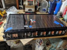
Some progress today.
I split the 8s and attached one side to a 10s.
I also bent up a small piece of copper to join the two sections of the pack. I'm not sure I am happy how that came out. I might try again to make something a bit more symmetrical.
I need to decide how I want to do the cell voltage taps on the second 4s pack as that end doesn't have the BMS connector.
Attachments
GXMnow
Solar Wizard
- Joined
- Jul 17, 2020
- Messages
- 2,700
I had no problem soldering to the tab at the bottom of each buss bar where it connects to the existing PC board. You do need a high power iron though. Something like 60 watts or more. My old Weller 60 watt soldering station worked great, but the heating element quit. My new iron is not quite enough, it claims to be 60 watts, but it is just a bit weak.
400bird
Solar Wizard
I was thinking of designing and ordering a circuit board with fuses similar to the factory board. But, as the saying goes, "Don't let the perfect stand in the way of the good" or something similar. I should just solder wires right onto the tabs.
My 200/300 watt Weller "gun" type soldering iron was struggling with those tabs.
But, the TS100 does roughly 30 watts and did better.
I don't understand that...
I was looking at the bus bar. The factory bar is 0.8 mm x 46 mm
I ordered copper sheet at 1 mm
I bent up a bus bar by hand and wasn't super happy with how it came out.
Then, I remembered hearing about someone 3d printing a form to bend the metal over in a press.
It worked great, much better than my hand made one and even better than I expected!

Of course, then I measured and calculated the area and ampacity.
1 mm x 47 mm = 47 mm2 (complicated math, right at my level, lol)
Depending on the chart I use, that is something between 2 awg and 0 awg. Rated for 100-170 amps.
Considering that I am fused at 250 amps and may end up running on a single pack if I am working on the other.
I designed and started printing a second form to bend a bus bar inside the first.
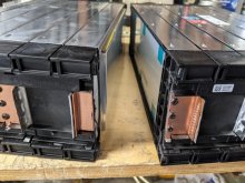
While that was printing, cut off the un needed stud on the end of the 10s pack.
It is only 18 mm wide?!

0.8 mm * 18 mm = 14.4 mm2
That is just barely larger than 6 awg (13.3 mm2)
6 awg is rated for 75 amps.
I guess there is no point in printing and bending the second bus bar to stack inside the larger one...
My 200/300 watt Weller "gun" type soldering iron was struggling with those tabs.
But, the TS100 does roughly 30 watts and did better.
I don't understand that...
I was looking at the bus bar. The factory bar is 0.8 mm x 46 mm
I ordered copper sheet at 1 mm
I bent up a bus bar by hand and wasn't super happy with how it came out.
Then, I remembered hearing about someone 3d printing a form to bend the metal over in a press.
It worked great, much better than my hand made one and even better than I expected!
Of course, then I measured and calculated the area and ampacity.
1 mm x 47 mm = 47 mm2 (complicated math, right at my level, lol)
Depending on the chart I use, that is something between 2 awg and 0 awg. Rated for 100-170 amps.
Considering that I am fused at 250 amps and may end up running on a single pack if I am working on the other.
I designed and started printing a second form to bend a bus bar inside the first.
While that was printing, cut off the un needed stud on the end of the 10s pack.
It is only 18 mm wide?!
0.8 mm * 18 mm = 14.4 mm2
That is just barely larger than 6 awg (13.3 mm2)
6 awg is rated for 75 amps.
I guess there is no point in printing and bending the second bus bar to stack inside the larger one...
400bird
Solar Wizard
Having cut off one of the end pieces, it's still copper inside, but it's coated in some other metal. My understanding is that this is often tin.
400bird
Solar Wizard
Work has me in Fresno on 4/30.
If you want to drive up and meet me there you could pick up 3 of the 10s packs.
I'll be covering Bakersfield for most of June. But, I only need to head down there if something fails and needs to be fixed.
I don't currently have any plans further south, but we can't always plan far out with work. I don't get to schedule parts failures and out of service events, lol.
400bird
Solar Wizard
My Bakersfield tech will be on vacation, so I'm providing emergency coverage for June. It's unlikely that I'll get more than one day notice when something breaks and needs attention.
I might find out one afternoon and then head down the following morning. A failure on a Friday would be best case to give a heads up.
I might find out one afternoon and then head down the following morning. A failure on a Friday would be best case to give a heads up.
This press is a great idea. I've been using a bending brake for mine, but they're not as sophisticated as your shape. Nicely done!I was thinking of designing and ordering a circuit board with fuses similar to the factory board. But, as the saying goes, "Don't let the perfect stand in the way of the good" or something similar. I should just solder wires right onto the tabs.
My 200/300 watt Weller "gun" type soldering iron was struggling with those tabs.
But, the TS100 does roughly 30 watts and did better.
I don't understand that...
I was looking at the bus bar. The factory bar is 0.8 mm x 46 mm
I ordered copper sheet at 1 mm
I bent up a bus bar by hand and wasn't super happy with how it came out.
Then, I remembered hearing about someone 3d printing a form to bend the metal over in a press.
It worked great, much better than my hand made one and even better than I expected!
View attachment 45952
Of course, then I measured and calculated the area and ampacity.
1 mm x 47 mm = 47 mm2 (complicated math, right at my level, lol)
Depending on the chart I use, that is something between 2 awg and 0 awg. Rated for 100-170 amps.
Considering that I am fused at 250 amps and may end up running on a single pack if I am working on the other.
I designed and started printing a second form to bend a bus bar inside the first.
While that was printing, cut off the un needed stud on the end of the 10s pack.
It is only 18 mm wide?!
View attachment 45953
0.8 mm * 18 mm = 14.4 mm2
That is just barely larger than 6 awg (13.3 mm2)
6 awg is rated for 75 amps.
I guess there is no point in printing and bending the second bus bar to stack inside the larger one...
1mm copper is a good idea. I've been testing my ~.7mm copper busses, and they're good, except for the connection between the 10s and the 4s (i.e. half of an 8s module) blocks. There, I have been losing ~20mV. This is similar to the problem as GMX described it in another thread, but I believe I am getting more voltage drop. I'm going to double up my busses at that connection soon and test again.
I am interested to know how your 1mm copper performs in terms of voltage drop at that connection.
400bird
Solar Wizard
Oh, I didn't notice this reply and already wrote something in your thread.
Thanks, the bus bar bending and form performance far exceed my expectations.
From memory GXMnow had less voltage drop on his connection from the 4s to 10s sections.
I'll post some voltage drop numbers once I get set up and can load test the pack.
Thanks, the bus bar bending and form performance far exceed my expectations.
From memory GXMnow had less voltage drop on his connection from the 4s to 10s sections.
I'll post some voltage drop numbers once I get set up and can load test the pack.
No problem. I saw your post there and responded there with a few more details for anyone reading through.
Yes, I remember that GXMnow had far less drop than I had. His 2/0 cables are probably less resistive even despite their longer length than my bus?
In any case, I'm grateful for his story, which made my diagnosis easy")
I'll look for your #'s whenever you have the chance to post them.
Yes, I remember that GXMnow had far less drop than I had. His 2/0 cables are probably less resistive even despite their longer length than my bus?
In any case, I'm grateful for his story, which made my diagnosis easy
I'll look for your #'s whenever you have the chance to post them.
GXMnow
Solar Wizard
- Joined
- Jul 17, 2020
- Messages
- 2,700
My plan is to eventually double the #2 cables (not 2/0) but for now I just added a #8 awg wire in parallel with the #2 awg cable, and it lowered the resistance enough that it is not a concern at my operating current. Here is a screen shot of my BMS operating at a 25 amp charge rate.

You can see that the two highest cells are still 10 and 11 due to the voltage drop from the cable instead of just a short buss bar. The resistance is causing the voltage to read higher while it is charging, and it reads lower while discharging. The difference is now less than 0.003 volts (3 millivolts) at 25 amps (the current reading on the BMS bounces from 22 to 27 due to the ripple current) that 3 mv is a difference of just 0.00012 ohms. The only reason this is any concern at all is so that the balancer does not erroneously start pulling from those cells while charging, and pushing back to those cells during discharge. I set the balancer to not try to balance until a cell is off by 0.006 volts. My maximum current is now about 80 amps during discharge. At this resistance, it might trigger a bit of balancing, but the times I pull that much is typically very short. When the microwave, vacuum, or hair dryer is running off the inverter. Most of the time it only 30 amps or less. Once I do double the cable with a second #2 awg, I think the total resistance will be vanishingly close to the buss bar.
You can see that the two highest cells are still 10 and 11 due to the voltage drop from the cable instead of just a short buss bar. The resistance is causing the voltage to read higher while it is charging, and it reads lower while discharging. The difference is now less than 0.003 volts (3 millivolts) at 25 amps (the current reading on the BMS bounces from 22 to 27 due to the ripple current) that 3 mv is a difference of just 0.00012 ohms. The only reason this is any concern at all is so that the balancer does not erroneously start pulling from those cells while charging, and pushing back to those cells during discharge. I set the balancer to not try to balance until a cell is off by 0.006 volts. My maximum current is now about 80 amps during discharge. At this resistance, it might trigger a bit of balancing, but the times I pull that much is typically very short. When the microwave, vacuum, or hair dryer is running off the inverter. Most of the time it only 30 amps or less. Once I do double the cable with a second #2 awg, I think the total resistance will be vanishingly close to the buss bar.
That is interesting. With another 2 AWG wire, it sounds like you'll be fine, esp. because of your test adding a 8 AWG wire - the cells are extremely well balanced even now, though. Better than mine, which differ by .003 V regularly. I wonder why my cell group #4 was reading lower during charging rather than higher like yours. On discharging with ~200 watt load, my cell group #4 was increasingly lower and lower than the other cell groups, which stayed within ~.003 V of one another. Maybe it is a difference in the way we've configured our cell groups? My REC bms (unlike yours mine has passive balancing only) was pulling all other cells down to let the one cell try to catch up at the top end of the 10 amp charging phase. The bms was heating up almost to shut-off limit (55c) during this attempt. I figured this would stress it like crazy with multiple cycles, so right away thought of your description and installed a 2/0 cable that seems to have completley fixed the problem - I just ran a discharge test with 1500 W load, and everything looks good. Next test for me will be doubling my bus and testing without the cable.My plan is to eventually double the #2 cables (not 2/0) but for now I just added a #8 awg wire in parallel with the #2 awg cable, and it lowered the resistance enough that it is not a concern at my operating current. Here is a screen shot of my BMS operating at a 25 amp charge rate.
View attachment 48783
You can see that the two highest cells are still 10 and 11 due to the voltage drop from the cable instead of just a short buss bar. The resistance is causing the voltage to read higher while it is charging, and it reads lower while discharging. The difference is now less than 0.003 volts (3 millivolts) at 25 amps (the current reading on the BMS bounces from 22 to 27 due to the ripple current) that 3 mv is a difference of just 0.00012 ohms. The only reason this is any concern at all is so that the balancer does not erroneously start pulling from those cells while charging, and pushing back to those cells during discharge. I set the balancer to not try to balance until a cell is off by 0.006 volts. My maximum current is now about 80 amps during discharge. At this resistance, it might trigger a bit of balancing, but the times I pull that much is typically very short. When the microwave, vacuum, or hair dryer is running off the inverter. Most of the time it only 30 amps or less. Once I do double the cable with a second #2 awg, I think the total resistance will be vanishingly close to the buss bar.
I've got an off-topic q. about Schneider Pro accessories, and did not want to insert into this thread, although you guys are Schneider Pro owners. If you have a minute, would you mind weighing in? Here's the thread: https://diysolarforum.com/threads/schneider-xw-pro-6848-accessories-q-s.22573/
Thanks, guys
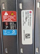
I managed to get a picture of the sticker on my 8S battery module. I can't get to the 10S ones the way I have them bolted together, just no room.
It actually does say LiMM-C.F / LGE just like your sticker shows.
I could have sworn it said LiMNC oh well. All the text online says they are NMC cells.
The date code on this one is 1901 So yes, week 01 of 2019 makes sense.
My top line shows: Model Name: Vista 2.0 Cell Module Assembly
Next line Rated energy: 4.75 KWH this is the 8S again.
180 AH x 8 x 3.7 = 5.328 KWH in a perfect world. LG/Chevy seem to be rating them at 90%
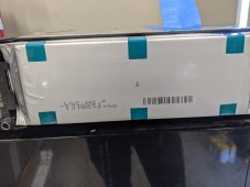
So, I went back and took another look at the stickers on mine. Here are some pics of the stickers and also of the cells that I exposed during surgery. Here's a close-up of the sticker, which labels the assembly as "Vista 2.0"

Here's a close-up of the print on the exposed cell, which reads, "LGZ N 2.1"


So, they're differentiating between the label of the assembly, which they call "Vista . . ." and the label on the individual cells, which are "N 2.1," at least in my modules. I checked my manufacture dates, which are 1807, 1808, and 1811, so older than both of yours. I, too, am concerned about the fire recall, and am just going to follow GXMnow's lead and charge to only 90%, keeping an eye on cell performance through my BMS. After a search, I found that Chevy is using some type of diagnostic software to detect faulty cells. I wonder how that could be different from the info we get through our BMS's . . .
Last edited:
400bird
Solar Wizard
Nice. These are definitely an upgrade. I would feel better about having the newer cells, too.
Last night, I was wondering why they have non-changeable fuses embedded in the pcb's on the modules that I am assuming just pin-out the cells for a bms. If the current controlled by the bms blows a fuse, what is supposed to happen to the bms function for those cells going forward? Is it possible that these fires come after a fuse has blown, thus eliminating the bms protection from that cell group? Or maybe the cell group just goes off-line, effectively removing it from the system? I admit that this musing is speculative and I don't have alot of needed variables like how the onboard Chevy bms works, but still it seems flawed to me to have non-changeable fuses in the modules' pcb's.
In any case, the N 2.2's look v nice and should serve you v. well !
400bird
Solar Wizard
Knowing how most car manufacturers work, a blown cell fuse would set a fault and likely disable the car entirely.
With the welded end tabs and series wiring there isn't a way to take one cell (or a group of cells) out of the circuit. So, if a cell monitor fuse blew, the BMS would see two 0 volt cells and be forced to cut HV.
With the welded end tabs and series wiring there isn't a way to take one cell (or a group of cells) out of the circuit. So, if a cell monitor fuse blew, the BMS would see two 0 volt cells and be forced to cut HV.
GXMnow
Solar Wizard
- Joined
- Jul 17, 2020
- Messages
- 2,700
I agree. The BMS in the car is probably very similar to what we use. If any cell goes out of range on voltage, temp, or current it probably opens the DC contactor and lights a warning to the driver. Maybe it will give you a minute to get pulled over before you are coasting. I have seen a few Tesla stories where they get a warning to pull over and park, and in 30 seconds or so, the car is dead.
Similar threads
- Replies
- 39
- Views
- 2K
- Replies
- 15
- Views
- 339