diy solar

diy solar

Adding storage to my Enphase system

I miss the simplicity of our old R-22 heat pump!
But after I had repaired/rebuilt it over 30+ years, it was time to move on.
The new compressor is a two stage, 4 ton Goodman DSZ16048.
Much more complicated!
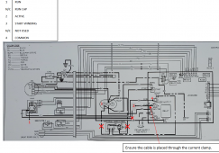
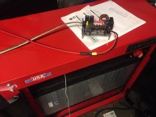
Here is a photo of the schematic inside the unit, w/ call-outs.
View attachment 58581
Sorry, I did not reply to this sooner. Looking at the "HIGH VOLTAGE AREA" it does look just like my simple Carrier unit. Just take out the "optional hard start" and you have a 3 wire compressor with a run capacitor. The only small issue I see is that you may need to get a separate HERM run capacitor for the compressor. Using the single dual capacitor for the fan as well, might pose a problem with the Sure Start box as it intercepts the common side of the capacitor.
 
Thank you very much, Gary!
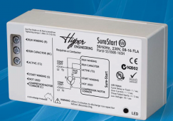
Looks like the Hyper Engineering device is some kind of VFD.
The "run" lead looks to is placed in series between the control board and the compressor.
So if I am reading this correctly, I put the "run winding-1" and "active-2" in series.
"start winding" goes to HERM-3.
The marked up schematic (red notations) that Hyper Engineering tech support sent me shows the run cap "N/C"?
Finally, looks like "Common- 4" connects to that lead on the control board.
Hoping to try this after it cools off here in December, so it I explode the heat pump, SWMBO will not be dealing w/ 90+ trempertures here!
Screen Shot 2021-09-06 at 17.36.16.png
Screen Shot 2021-09-06 at 17.43.34.png
 
Well, too bad I did not get my second battery bank connected into the system yet, but I can tonight after work if needed.

Why I am saying that? The power just went out as I was getting ready to go to work.

I had just told the Schneider XW-Pro to start charging for the day. And I was answering a few e-mails etc., and I saw the status page show the battery discharging, instead of charging, did not even notice the power was out, Hmmm. The XW took over and was running everything just fine, but it was using battery power. So I checked, and the Enphase solar was acting odd. Production was only at 300 watts, not enough to keep up with the loads, so the battery was helping out. The sun is still quite low, but when I looked, only 5 panels were making power, the other 11 were in "Grid Instability" shut down again. I waited more than 5 minutes, but they didn't wake up. A few came on and back off as I watched, but it was not looking good. So I went ahead and changed the inverter grid profiles back to CA Rule 21 as a profile change does reset the inverters. It worked, all 16 are back producing, and I am now running most of my home, and charging the battery at 700 watts at just 9 am. Production is a little behind yesterday, but not too bad. At this time, every panel is now making over 90 watts. One panel just tripped a frequency out of range grid instability error, but the array is still making 1,500 watts, and it still says all 16 are producing power. Once I am sure the system is stable, I have to head to work.
 
Glad to hear you solved the tech issue quickly!
I recently learned a tiny bit about the concept of AC coupling.
After reading your post and looking @ your equipment listing, I am guessing you are using
AC Coupling technology.
I am set up DC coupled, off grid.
As I learn more about AC Coupling w/ the XW Pro, I might try to add some AC Coupled PV in the future, as my Conext 100A-600V MPPT charge controller will be maxed out for volts and amps when I add more panels to that array this Winter.
 
It certainly is fascinating to see this and hear about it. Local electric rates in our area are going up 5 percent again, today!
 
Yes, my system is AC coupled with Enphase iQ7 microinverters and the Schneider XW-Pro battery inverter.

The power was out for just under 90 minutes, so it was not a long outage. The iQ7 inverters did see the power glitch, and 11 of them shut down, but 5 of them stayed making power right through the failure. 4 more did start producing on their own, bringing it to 9 up and 7 locked out after 5 minutes. Since my network is all on the battery backup, I was able to log into the system right away and by changing the grid profile, the rest of the iQ7 inverters came back online and were producing power.

My 18 KWH battery bank was at 51 volts after running my home last night. The battery had just started to charge at 8:36 am, and the power cut at 8:38, so I only got 2 minutes of charging before the power cut. The battery voltage only climbed to 51.06 volts in that 2 minutes, and then the battery was forced to run the house with only about 140 watts coming in from the solar panels as it was still very early, and 11 were not producing at all. At 8:49 I did the grid profile update and one by one, all of the iQ7 inverters came back online. I saw the power ramp up until the battery current dropped to about zero. And by 9 am as the sun was getting a little higher in the sky with all 16 inverters running, the solar took over running the house, and started pushing power back into the batteries. At the lowest, the battery only fell to 50.89 volts before the system started charging. At 9 am, it was charging at 13 amps. As the sun came up, it ramped up with the charge current reaching 23 amps which is where I had it set to limit. It looks like frequency shift worked, as I see the charge current dip off and ramp back up 4 times. Each dip exactly 10 minutes apart.

The grid power looks like it came back on about 10:03 am as the current went to dead flat 23.37 amps from there on. The battery voltage was up to 51.65 volts before the grid came up, so it was certainly charging in AC coupled. Looking at the logs from the Enphase system, it looks like the clocks are about 4 minutes out of sync. They show the grid frequency high messages at 9:25 9:35 9:45 and 9:55. It does not really show in the battery current graph, but a few inverters also cycled off at 9:15 also.

This is where it gets a bit odd. The same 5 serial numbers are the ones that kept seeing the "Grid Instability". All 4 times, it was the same 5 inverters, the other 11 did not store any log entries for stability issues. I wonder if I should ask Enphase about replacing those 5 for being too picky? But they did not stay off a full 5 minutes either. The dip in charge power is less than 2 minutes every time. So it looks like they were maybe just curtailing a little and when the charge current fell, the frequency ramped back and their power went back up. In any case, the system worked perfectly from the outside. Without looking at the data, you would have no idea it even went to backup power.

Once the power came back up, it resumed charging at the fixed 23.37 amps (17%) and the battery reached my full charge setting of 57.4 volts at 3:29 pm. At 4 pm, it switched to "grid support" and is still running all of my loads and exporting a little to grid at the high time of use rate.
 
The same 5 serial numbers are the ones that kept seeing the "Grid Instability". All 4 times, it was the same 5 inverters...
I opened a few tickets asking about what was going on with mine and never saw any traction until the battery started misbehaving. Then they replaced a few. I still see some grid instability messages, but it's not the same ones every day multiple times per day. Even then I never really worried about too much with the software upgrade as the reset meant I was only out about one panel's worth of power for 5 minutes.

Doesn't hurt to open a ticket and ask though IMO.
 
With my Enphase iQ7's, I never see any error messages except when it is running off grid from the Schneider, and f course, Enphase says, well there's your problem. The XW-Pro output is pretty rock solid, but I guess it does have a little micro stutter as my cheapo LED lights do have a noticeable odd flicker. All of my better equipment has no issues, and looing at a scope, the waveform looks cleaner than our grid here. So as long as I am seeing them self reset and keep producing, I am not going to complain too much.

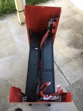
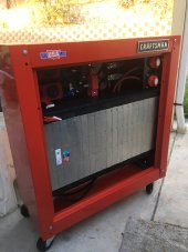
I completed the second battery bank, and got the casing all completed. It was certainly a bit of a pain getting a few of the bolts in. The batteries take up so much room in the cabinet, I can't get my hands into the back side to hold the nuts, so I ended up gluing the nuts inside the cabinet before screwing on the next panel. It worked pretty good, but I wish I hade a Rivnut system to install kept nuts.

SO I am ready to connect it and double my capacity, BUT.... The new battery bank is charged higher than I ever run my system. I rigged up my little step down buck regulator to pull power from the new battery and push it into the old one. Right now it is pushing 4 amps between the two batteries. It will probably take about 2 days to get them equalized before I can flip on the disconnect switches in the new battery bank. But I am not wasting any power. It will keep charging the old battery from the new one all night. Th only small problem I have is that my cables are connecting the negative, so the buck converter is not seeing any current flow. It uses a shunt on the negative, Oops. So I adjusted the voltage through a #22 gauge wire to produce the 4 amps, but it is not regulated. As the old battery is drawn down the current will increase, and as it charges up the current will decrease. I have it fused at 10 amps, just in case. But yeah, 4 amps out of a 360 amp hour battery is nothing.
 
Since the #22 wire is still a very low resistance, as the voltage difference changed, the current was changing way too much, and the buck converter was getting hot and the fan was not coming on.

So I unplugged the 350 amp Anderson connector, and connected the negative through the buck converter shunt resistor. As soon as the current topped about 1.5 amps, it turns on the fan. And now it is running in constant current mode at 4.00 amps. Since both batteries are 360 amp hours, I set the voltage limit to half way between the 2 packs, 53.5 volts now. 51 volts to 56 volts. The inverter is still pulling 12 amps from the system, but now 4 of those amps are coming from the new battery, and 8 amps from the original set.
IMG_9845.JPG
doing a little math on my graphs, it looks like my old battery would climb just under 1 volt per hour when charging at 23 amps. So 23 amp hours raises the voltage 1 volt, give or take. NMC cells are very different from LFP cells, that's for sure. So to climb the 2.5 volts I am looking for, I need 2.5 x 23 = 57.5 amp hours. At 4 amps, that would be 57.5 / 4 = 14.375 hours to go. It is now just after 11 pm, tomorrow, around 1 pm, they should be getting pretty close. Actually, once I kick on the XW-Pro into charge mode, it will bring up the old pack a bit quicker, so I will just watch it when it is close. When the old pack matches the new one, I can turn on the disconnect switches and have my full 36 kilowatt hours all connected. 720 amp hours of storage.

Now I really need those extra solar panels for some DC charge power. I will hardly be cycling these things without it. I will still only be moving about 8 to 10 KWH per day at best, but I will now have another 20 KWHs of backup power if we do lose power again. I will also experiment with move more load onto the inverter. My only concern now is if my air compressor starts at the same time the microwave and toaster are in use. And don't forget the refrigerator as well.
 
So I went to check in on the state of the batteries this morning. I expected the old pack to have been pulled up 1.2 to 1.6 volts, but it was only up 0.2 volts. Hmmm, did my little buck converter fry? I go out to the garage, and it is still pushing 4 amps. So what's up?

I check the voltage of the new battery, and it has ben pulled down the expected 1.5 volts. I know the Schneider XW-Pro does have some parasitic draw, but it should not be that much. So I open the logs, no problems, no grid failure. Then I open the battery summary graph, and it slaps me in the face. At 3:34 am the battery voltage was pulled up above 51.06 volts, so the inverter went back into "grid support" mode and started running the loads in the backup panel again. It was pulling over 11 .5 amps for 90 minutes until the battery again dropped below 51.0 volts. So that is another 17.25 amp hours x 51 volts = 879 watt hours that it put into my house. And that power all came from the new batteries that are now down to about 55.3 volts as it continues to push 4 amps into the old battery.

So at this point, I think I just have to wait until the XW charges the old battery up to 55 volts to connect the new pack.
 
Buck - from what higher voltage to what lower? May or may not require some voltage headroom to operate.

How about just a resistor, like a suitable length of wire, between the backs to equalize them?
 
Great progress. You beat me to it, I haven't connected the second pair on batteries yet.

But my plan is to get my old packs up to 4.1 volts/cell (finish absorption) and disconnect it.
Then connect the new packs and directly use the energy. I'll probably swap in the even so I'll start by pulling the new pack down overnight. Then let it charge and absorb the next day. At that point they should both be at very similar SOC and voltage, then connect all 4 packs.
 
Hedges,
My buck converter is a DROK I got off of Amazon. It is rated at up to 80 volts and 10 amps, not to exceed 500 watts. It does need about a half volt drop to work stable, but at low current, I did see it work at just a 0.1 volt drop. It is working flawlessly at 2.5 volts difference (55 to 52.5 volts) at 4 amps.

If my system would sit for a full day without cycling, I could probably do the resistor idea, but since I am cycling, I have to chase the constant changing voltage of the current pack. That is where I am right now. I am watching the voltage as it is charging now, and when it gets within 0.1 volts to my new pack, I will tie them together and watch the current. Even the 0.1 volt difference might cause close to a 100 amp current between the 2 packs though, so I have to watch it to make sure I don't pop any expensive fuses. Each string is fused at 100 amps. The new pack is 2 strings. There is about 5 feet of #2 awg wire on each string, and then they combine to about 15 feet of 2/0 cable and the 350 amp Anderson connector between the 2 banks. I am fairly sure the Daly BMS units will provide at least the 0.001 ohms needed to limit the current below 100 amps at 0.1 volt difference, so I should be good to go.

At this moment, the new battery has been pulled down to 55.4 volts, and the old battery is charging up and just reached 52.9 volts. I am getting 20.9 amps from the XW and another 4 amps still coming in from the new battery, so I am very close to the 1 volt per hour slope. So in less than 2.5 hours the two banks should be within 0.1 volts. I am watching them pretty close now. If I do miss the crossover point, I will only have to wait until tonight when the old battery is running the house and coming down in voltage to catch the crossover point again. The only reason I had to actively pull power from the new battery is that it was charged higher than I run my system when I received the cells. Evidently, the car was fully charged right before it was totaled.

440bird,
I had thought about that too. I could have just set my XW to charge the old bank to the same voltage as the new cells, and then connected them, but with the increasing news on the Chevy Bolt battery recall, I just didn't want to push my older LG Vista 2.1 cells up to 4.11 volts per cell. Once both banks are connected, I will drop my full charge voltage to 4.05 volts per cell. 56.7 volts max, should be safe. My charge rate will still be under 30 amps total so each string will only be getting 7.5 amps. Once I add the DC solar then my charge current could hit 62 amps peak, but even that is only 15.5 amps per string. The cells are rated for 180 amps per string, so less than 0.1 C on 1C rated cells. Since I don't plan to cycle much more, I will likely raise the shut off voltage a little also. I may eliminate charging on the XW completely, and just have my microcontroller turn on my stand alone 10 amp charger when the Enphase system is exporting more than 1,000 watts to the grid. That could push my peak charge current to 70 amps. It is all still a bit of a balancing experiment.
 
SUCCESS!!

The battery voltages converged at 54.9 volts. My Fluke 76 will only go to .1 volt resolution over 40 volts, so I plugged in the Anderson connector, and measured the difference across the disconnect switches, and they were under 0.07 volts. I flipped them on and saw no change in the charge current or voltage reported by the XW. The BMS in the old battery bank showed a small drop in charge current. After the system was at rest like this for about 30 minutes, I checked all 4 strings of cells with my old clamp on amp meter. The two old battery strings are each pulling 7 amps, and the two new strings are pulling 4 amps. This should balance out fairly quick as the older pack will charge up a little faster and the currents should balance. The total charge current is 22 amps, so the math works. I did not demag and zero the amp meter, and trying to see less than 1 amp on a 200 amp clamp meter is kind of pointless. I mainly wanted to be sure I didn't have a huge current flowing from one battery to the other. All 4 strings are charging, getting power from the XW.

Another fun data point... The second battery has now been connected about 30 minutes, so I looked at the battery summary graph, and you can clearly see the voltage climb rate is about half what it was with just the old bank, so that also shows the same charge current is now charging double the capacity.

When it goes into discharge mode tonight, I will check the current balance again, and also check the voltage drop on the Daly BMS units vs the one JK BMS on the other 2 strings. My JK is rated at 200 amps, and the pair of Dalys are rated at 100 amps each, so I would hope the total resistance is fairly close. The Daly units have a lot more heat sink area, but I made up for that with the extra heat sink I added to my JK. The wire sizing is also the same. The JK has a pair of #5 wires for the in and out, and each Daly has a single #5 for the in and out. The old battery bank has a 125 amp fuse on each string, the new bank has a 100 amp on each string. The cable from the inverter to the new bank is longer, so it should lag a little behind. I am not concerned about that. I know the current will not perfectly balance. Since I am pulling so much less power than the bank can handle, the balance is not going to cause a problem.
 
It has now been charging just over 90 minutes and the charge currents between the two banks have balanced out. In fact the new bank is pulling slightly more current than the old batteries now. I even did the zero out on the amp clamp and it looks like the new batteries are taking about 5% more current now.
 
In one of my news feeds, I received an update about the Chevy Bolt battery fire investigation. This seems to be good news for those of us using the Chevy Bolt battery modules for solar storage.

In the battery modules that have caught fire, they identified that a cell appeared to have 2 failures effecting the same cell. The difficult one is that the separator sheet inside the cell had a fold in it. That causes a high spot which concentrates some load on a much smaller part of the cell. The cells are restrained from expansion when the cells charge, discharge, heat, and cool. If they expand and there is a fold in the separator, it can cause localized pressure. But it seems that alone is not enough to cause an internal short in normal operation. The other fault is that a few cells seem to have tears in the tabs. This may have happened when the robot is spot welding the tabs together. A minor tear in the tab does not show up in electrical testing, but when high current is run through the cell for fast charging or hard acceleration, the torn tab will have more resistance which will cause localized heating. If you combine this localized heat in the same cell that has a folded separator, not you have a problem. The cell expands a little more, which steps up the pressure and can lead to a short pushing through the separator.

So why do I say this is "good news"? Well, 2 reasons in my mind. When I soldered on my balance leads, I looked at every cell tab, and I did not see any that showed even the slightest damage. If one of the tabs was torn, even half way though, the result is a bit of an increase in series resistance. In the car, they only run 3 cells in parallel. So one bad tab is seeing 1/3 of the current flow. In my original battery install, I double that to 6 cells in parallel, and now I am at 12 cells in parallel. A single bad tab is seeing only 1/12th of my current flow. The highest current I have hit yet is just 80 amps. If I add the DC charging, and crank up my system, I will still never hit 200 amps. So I will never push more than 16 amps to any single cell. and if a cell tab is badly damaged, the other 11 in parallel will not be overly stressed. With how good my cell balance is holding, I truly doubt my original packs had any of these flaws in them. I would expect a flawed cell to not hold balance though the charge range, but they all do. My new cell banks are the later Gen 2.2 cells which were more carefully inspected as GM was already aware of the first issue. I did notice the tabs were a fair bit longer than my old set. To the point where the covers over the tabs were hitting the tabs. I carefully bent the very top of the cell tabs over so the buss bar covers would fully seat. It appears that when they installed the buss bar covers, they pressed them in and flexed the tabs a bit to make the snaps catch. That was putting an odd stress into the tabs. I think most of it was just flexing the plastic cover outwards, but it was enough, that I could not push the cover if far enough for it to snap in with just one hand, like I could easily with my first packs. I have eliminated that issue.

When you combine all that with the fact we are using less than 50% of the capacity, I really don't think we have anything to fear about these cells catching fire. Now that I doubled my capacity, I reduced my full charge to 4.05 volts per cell or 56.7 volts for the 14S Li NMC pack. And I also raised my low voltage shut down for daily cycling. My system goes into standby when the cells are at 3.78 volts (53 volts for the whole pack). That is well above the 50% point. I may lower both voltages a little more even to get the same cycle capacity, but closer to the 50 point in the cells. Heat seems to be the big enemy. With the current we use, especially with my doubled up pack, there is no heating due to current. I have temp sensors on each battery brick now, and they never are more than 2 degrees above the air temp in my garage, and most of the day, they are actually cooler.

Here is one of the article links I was able to copy.
This is the oldest one that mentions the dual failure on a single cell.
 
There has been a bit of talk about AC coupling with Enphase micros and the XW-Pro, so I figured I would poke around a bit more with what happened when my grid did fail last week. Here are the screen shots of the whole day from both Schneider and Enphase.
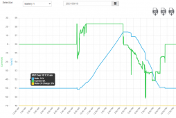
XW-Pro_grid-failure.PNG EnphaseGidFailure.PNG

Showing the whole day, it is a bit hard to see what really happened, so here is a zoom in of the entire time the power was out, about 90 minutes from 8:38 am to 10:03 am
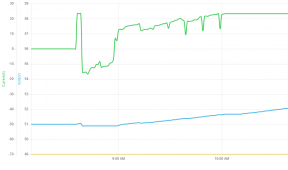
GridFailZoom.PNG

At 8:35, I had just started the XW-Pro charging. You can see the charge current goes from 0 to 23.38 amps. But just 3 minutes later, at 8:38, the current goes to -15.49 amps, discharging the battery. After 5 minutes a few of the iQ7's start to come back on, but at 8:44 am, each panel is making less than 20 watts. So even with 5 panels running, I am discharging. I go around and turn off a few devices to reduce my load a bit, but at 8:50 my refrigerator cycles back on. You can see the discharge current was ramping up towards zero, but then stepped down a bit again. This is about when I sent the command to the Enphase system to change the grid profile, and all 16 panels started producing power again. By 8:58, I was charging at 7 amps, and ramping up as the sun was rising.

At this point, just after 9 am, I had to leave, I was already running late for work, so the rest is all unattended operation.

It looks like the refrigerator cycled on again about 9:13 am. The solar power is still ramping up, then I see a tiny dip at 9:20. I would say it was something turning on, so I ignored that at first. The charge current keeps ramping up with the rising sun, an all looks great. Then another dip at 9:29 am. This one is a little deeper, still only 1 minute long, no big deal. Then again at 9:39 and 9:49, and 9:59. Hmmm.

I looked in the logs on the Enphase system, and sure enough, at perfect 10 minute spaced intervals, 5 of the iQ7's showed a grid frequency too high instability, but it cleared in one minute. The charge current on the graph never quite hits my setting, but it is obviously rising close to my max current, so I am quite sure, that was the XW-Pro shifting the frequency to limit the current, and it did work just fine. It does look like the grid came back on at 10:03 am as that is where the battery charge current went dead flat at my 23.35 amp setting. As the solar continued to ramp up, the extra power was then being exported out to the grid. The battery voltage goes back to a very linear climb as it charges at the fixed current.

It would have been nice if I didn't have to work and I could have put my frequency counter and scope on the system, but the data log does tell it pretty well. I also should have dialed the max charge current up. I have it set low when I am on grid as I have until 4 pm to get the battery charged. I am not in any hurry, and the extra power does credit my bill. I end up exporting about 40% of what I did before having the battery bank. But off grid, I hate to just throw away the power like that. And if clouds moved in later, it would be nice to just grab all the solar power I can until the battery is full. I think the newer Schneider firmware does have a few extra settings for on vs off grid. I am still on 1.08 and it only has the one current setting. Even just my old battery bank could easily handle the full 140 amps the XW-Pro could push out to the batteries, and now with my doubled battery bank, it is no sweat at all.
 
@GXMnow Always fun to read your posts. You really have made a number of remarkable examinations of the varying quirks and benefits of Schneider/Enphase equipment (including this one). One of the great benefits of Schneider is their robust graphing and data logging - it lets a user keep a close eye on their system (current & historical). And the AC Coupling side of the Schneider software is really quite versatile - when combined with a Schneider DC coupled SCC it's hard to beat. (I have a Conext SW4024 - AC and DC coupled with old school Enphase Micros). Best.
 
We had another power failure on 9/21 at 7PM. This one was a bit odd. The Schneider XW-Pro log file lists it as a "AI Under Frequency". A I is Anti Islanding, meaning it had to open the contactor to the grid. But under frequency is odd. The power did go completely out, all the neighbors houses also went dark. The sun was nearly set, so my solar was only making less than 100 watts total out of all 16 panels, so not much to go on, so it just used battery power to keep my essential loads panel up and running. So I can't really tell if it knocked any of the Enphase iQ7s offline this time.

But what made this one odd is that my internet router crashed and had to reboot. It has stayed running through every previous power glitch without a problem. It did reboot by itself, and the computers, and even the Enphase Envoy all got internet access back quickly, but I still have several devices using DHCP, including the Schneider Gateway. And since I talk to it on the local network by using it's ip address, it seemed to have vanished. I even went into the router DHCP log, and it was not there. Hmmm. The inverter was up, powering the loads, showing about 1,800 watts on the local display, and the lights on the gateway appeared to show some activity, but in the end, I had to also reboot the gateway. When it came back up, the router assigned it a new ip address, so I had to go in and change the ip address for my web browser links and for my PLC to talk to it, I really need to make that a fixed ip address.

Once I was able to log back into the Schneider gateway, I was able to clearly see where the power went out in the data log. It did not lose any of the data except for the 2 minutes when I rebooted the gateway.

What makes this one look very odd is that the fail at 7 pm looks like it switched clean. It was exporting about 800 watts back to my main panel when the power failed, so the battery current actually dropped from 30 amps to just 16 amps to keep running only the loads in the backup panel. The current varied a bit with the loads in the house, hitting up to 26 amps, but then at 8:41 pm, the battery current drops to 0. This appears to be when the grid power came back up. So the transfer switch closed again, and the loads are being supplied by the grid, but the inverter went fully off, it should have still been helping to run the backup loads. It does wait the required 5 minutes before it will export back out of the input side. But in this case, te battery current stayed at zero for the full 5 minutes. Not really a big deal, but I had to pay for that power at the peak time of use rate. Then at 8:47 the inverter kicked back in and resumed running the backup loads, and pushing 900 watts back to the main panel again. Battery current jumps to almost 40 amps, an ramps to 42 amps at one point, just before 9 pm. Then at 9 pm, I have it programmed to stop selling to grid, or in my case, back feeding the main panel. So the current drops back down under 20 amps to just supply the loads in the backup panel.

My guess is the router crashed when the grid came back up and the inverter shut off. Everything else looks completely normal. The inverter stayed running the backup loads until 11:37 pm when the battery ran down to 52.75 volts, where I have it stop running grid support.
 
Back
Top