diy solar

diy solar

Advice for an off grid 12v system.

tastiger

New Member
Joined
Dec 12, 2019
Messages
6
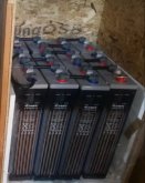
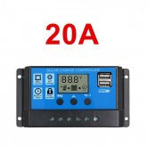
Hi all, I am expected to set up a system that I am very doubtful about. Supplied to me are 12 large 2volt 680ah wet cells, 10 cheap blue twenty amp controller and ten generic 200 watt panels.

Owner expects a controller to connect to a panel then the ten will be paralleled to the batteries set up as 12 volt.
Any sugestions for common sence appreciated.
s-l1600.jpg20191215_181417.jpgimages (10).jpeg
 
So as 12v thats 4 cells to a battery . So 3 of those in parallel 4s 3p or 3p 4s your choice.

1 controller per panel means the controller will probably get enough voltage to start up .
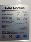
  • Max Solar Panel input: 25V(for 12V battery) from specs.
What is the panel voltage output . The Vmp?
 
Last edited:
Cells are 2 volts each, 6 in series 2 parallel planned. Photo in box is a representation of the type.

Resized_Resized_20190908_191155_2768.jpg
 
So as 12v thats 4 cells to a battery . So 3 of those in parallel 4s 3p or 3p 4s your choice.

1 controller per panel means the controller will probably get enough voltage to start up .
  • Max Solar Panel input: 25V(for 12V battery) from specs.
What is the panel voltage output . The Vmp?
I see 12 Flooded Lead Acid cells. The chemistry dictates 6 cells are needed to form 1 12 volt battery. My math also confirms this (2*6=12)
Supplied to me are 12 large 2volt 680ah wet cells, 10 cheap blue twenty amp controller and ten generic 200 watt panels.
I'd configure the cells 6s2p & install a 2 bank battery isolator switch. Now a single cell failure can be isolated by switching out the bad bank.
Your (OP) biggest hurdle is handling the charge current (<300 115 amps) during peak production. Small imbalances can lead to large consequences. With 10 PWM controllers in the plan there will be a whole lot a switching going on. Looks like they are not designed to coordinate either.
I'm curious to find out what happens when 2Kw of solar being produced runs into those cells in the top half of their charge curve.
 
Last edited:
I concur with SCClockDr. Since you want a 12 volt battery and your cells are 2v each, you need to put 6 cells in "series". Since you have 12 cells, that two parallel banks; aka 6s2p. See the Battery FAQ for more.

I'm afraid April's configuration of 4s3p would only give you (4x2 = ) 8v.

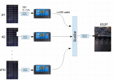
You have 10 PWM SCCs? Usually you'd use an MPPT and put the solar panels in serial/parallel to get the amps/voltage (see the FAQ if that doesn't makes sense)needed - it lowers the wiring costs. Well, 10 panels and 10 SCCs something like this:

Capture.PNG
11.11x1.53 = ~17 amps for the breaker but rounded up to 18 as I'm not sure you could get a 17 amp breaker. The owner will probably tell you the SCCs are too cheap to protect with a breaker and not worth it, but they're also there to act as a disconnect. ditto the 180A breaker to the panel. If they're not up for breakers see if they'll at least let you put switches in. Might want to verify the SCCs have blocking diodes (they usually do, but if these are super cheap they might not). Without a diode they'll drain the batteries at night (to check, see if there's voltage on the solar side when the panel is disconnected, if so you'll need to add blocking diodes).

Each battery bank would be getting just under 90 amps at full solar, so be sure to verify that is under the C-Rate for your cells.

Check out the wiring FAQ to get the wire sizes based on amps and distance and the battery FAQ also has tips for wiring terminals in parallel to resolve internal resistance issues.

Anyone else see anything that might be needed?
 
Last edited:
Distance PV's to SCC's? Times 20 & SCC's to the buss bar times 12?
Buss bar to Isolator switch times 2?
Isolator switch to the battery banks times 4?
Praying these are short or a lot of wire will be needed.
 
...Praying these are short or a lot of wire will be needed...
My bet is whoever put it together didn't consider the wiring costs. Of course, if the distances are small at only 12 amps perhaps the wiring will be cheap enough to justify it. It would be interesting to see a cost analysis to see if it's genius or not. One things for sure, it would be easy to expand if the busbar was pre-planned to be big enough.

I'm guessing from the Thylacine icon that Tastiger is in Australia/Tasmania? In which case you'd also need to follow any NECA rules; no clue what those might be (e.g., negative grounded).
 
Thanks for the advice. The two banks of six was being planned, just trying to convince the owner to go a simpler way with less components and mppt.
 
Hopefully you're getting paid by the hour on this job. ?
 
Oh hell no.

Id do a single 60-80A mppt in a 24v config.
 
Last edited:
You never know, he might have 1000' of 10 gauge he got in the 80's when copper was cheap that he wants used up. Wait until tastiger learns his friend also wants him to lace the cables rather than zip ties because he also has 3000' of paracord to use up. ?
 
It's a unique situation here, that's why it is in the middle of nowhere. All lacing will be of kangaroo leather?
 
Back
Top