diy solar

diy solar

Advice for non-solar power box / electric generator

krby

Solar Enthusiast
Joined
Nov 2, 2019
Messages
266
Location
SF Bay Area, CA
UPDATE: I'm posting updated parts and diagrams in the thread as I go, leaving the existing drawings in place so the thread makes sense.

In another thread, someone suggested I could post here for advice.

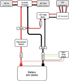
I'm building a portable electric generator similar to Goal Zero or Kodiak but without the solar charging capabilities. It's basically a battery bank, a charger, and an inverter in a portable box, probably one with wheels on it. We'll use it at home during blackouts, while camping, and for charging batteries on R/C flying. I'll start off with the my first attempt at a wiring diagram:
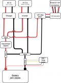
24V power box v1.png

I'll charge it from house AC and leave it charged most of the time. When "in use", I'll move it close to the load, and plug the load into an AC socket the box. I know I'm not taking great care of the batteries by leaving them charged most of the time, I expect maybe a few hundred cycles over maybe 5 years. I'll definitely store the box somewhere Part of motivation for building this is the project itself, so replacing batteries in few years may happen anyway as part of upgrading.

I've spent some time sizing the loads and have settled on ~4kWh and 2000W of power. Here's how I got there:
1) The worst case power draw will be ~1300W for a hair dryer or ~1000W charing R/C batteries.
2) The fridge plus other things we might want powered during a blackout take no more 1.5kWh a day, I'd like at least two days plus some headroom.

Here are the component I've spec'd out so far. I'm thinking I will purchase the large expensive bits (battery, charger, inverter, wiring, big fuse) get an idea of placement and size and then start looking at boxes before I buy any of the exterior parts.

24V 200Ah LFE battery
I'm focused on LFE because I want this to be lighter and smaller than I can get with SLA. Right now a 24V 200Ah from Specialized Power/Pacific Sun Systems is the front runner.

2000W Pure Sine Inverter
I haven't made a choice here, open to ideas.

24V LFE battery charger
Something like 25-50A feels like it would be good. 50A is a 0.25C charge rate on the battery bank. I'd consider an inverter/charger, or one of the all-in-one units Will has talked about and just not use the solar input. I don't need the automatic transfer feature, but saving money and space would be nice.

150A or 200A Fuse
The 24V/2000W inverters I've looked range from about 120-133A of max DC input, so rounding up to 150 or 200A. 150 might be cutting it close. In the attached drawing, I have only one fuse, do I need one each for the charger and the inverter? Or will those each have their own?

Wiring
somewhere between 2 and 2/0. Using this calculator
https://www.powerstream.com/Wire_Size.htm, and punching in 6ft, 150A, 24VDC. 2AWG gives a 1.2% drop, 2/0 gives 0.6% drop. I expect the actual distance to be shorter. Have I done this right? I'm fine buying slightly bigger wire, but because this is all going in a box I will need some tight bends.

Battery disconnect / Main switch
I think I need like some sort of disconnect that I can switch manually. Something switch that disconnects the battery from everything. Right now I'm looking at the regular Blue Sea switches that boat and RV folks use. But maybe something like the Sterling ProLatch or maybe just a relay with a switch mounted outside the box?

12V stepdown
12V is useful for a variety of things, I'll wire this up to various DC connectors like banana posts, PowerPole, maybe a "cigarette lighter" socket.

Fuse(s) for 12V outputs
For the 12V output, the wiring and connector ratings will be much lower than the main 200A fuse. Do I need a fuse per connector or can I use a single fuse between the output side of the 12V step-down? I can imagine using 10A on some PowerPoles.

AC Input
IEC socket for charger input, or just a regular cord.

AC Output
1 or 2 NEMA 15A AC sockets for the inverter output.

Switch(s) to control inverter and/or charger?
Not sure I need to control these separately on the outside. For ease of use, just one master switch might do it. Since this will be sitting for months at a time, I definitely don't want the inverter on all the time. Maybe this could just be the battery disconnect?

Volt / Amp power meter
I think I could do just volts, but I like the idea of a panel mounted display for amps. Will suggests a baylight one on Amazon, but I'm going to need 150-200A, right? I'm assuming I don't need to monitor the charging side, just a shunt on the output side, right?

I'm hoping the folks here can look everything over, point out what I'm missing or give whatever other advice they have. Thanks!
 
Last edited:
The only thing I can see.... if for some reason the fuse pops on the battery, there is nothing between the charger and the inverter. If the charger and inverter are both on, the inverter could draw more than the charger can satisfy, good chance of damage if the inverter doesn't have or invoke some kind of protection. Same thing with the step-down, in the event of battery failure, the entire 12VDC load comes from the charger.
 
The only thing I can see.... if for some reason the fuse pops on the battery, there is nothing between the charger and the inverter. If the charger and inverter are both on, the inverter could draw more than the charger can satisfy, good chance of damage if the inverter doesn't have or invoke some kind of protection. Same thing with the step-down, in the event of battery failure, the entire 12VDC load comes from the charger.

Thanks for the feedback! So I need to either make sure the charger has it's own protection, or just suck it up and one fuse for each of the three charger, inverter, and step-down, each sized appropriately.
 
Chargers usually have some kind of protection, it would be a matter of making sure it's adequate and would actually protect under those circumstances. Under fail conditions, you'd get a big sag in voltage as the charger tries to satisfy, but maybe not enough current to pop an in-line fuse.

Or just leave it be, and be aware, make a mental operational procedure not to hook up the charger while drawing loads, or whatever fits your needs.
 
How about an ATS so when the AC IN is connected the AC OUT won't be connected to the inverter? Or even better, an Inverter with an ATS and Charger built in? The links aren't meant to be hardware recommendations (don't know much about the hardware); just examples of the device types.
 
How about an ATS so when the AC IN is connected the AC OUT won't be connected to the inverter? Or even better, an Inverter with an ATS and Charger built in?
I don’t really need the ATS. The box will be plugged in to charge then stored for weeks, then moved to where it is needed and the ac out used. One reason I am considering an inverter charger is to keep wiring simple and keep overall size down. I need to price out vs individual components though.
 
Simple Answer with a KISS solution.

2200 Watt Pure Sine Inverter/Charger https://samlexamerica.com/products/ProductDetail.aspx?pid=574
AC Inputs
  • Two separate AC inputs – one for grid (priority #1), one for generator (priority #2), connect simultaneously, no need to reconfigure when different power sources are available.
  • Generator Input is specifically designed to have more tolerance for wave form distortion, prevents unnecessary “rejection of AC input and switch to inverter” by tolerating distorted wave forms that can be produced by gritty generators
  • Each AC input is programmable for voltage and frequency. User determines what the min and max thresholds are to switch from Grid or Generator to Inverter.
  • Generator start can be initiated by “Status Relay” contact, can be programmed to activate when grid is lost.
Solar Input
  • Connect a solar charge controller directly to the EVOTM though the Battery Charger external DC Input, seamlessly integrates solar charging into the EVO’s power system.
  • ONLINE Mode can be used to prioritize Batteries/Inverter over the grid, ideal for those wishing to operate primarily on solar power (when the grid is available, but might be costly).
Battery Charger
  • 3 or 4 stage charging with Equalization (must be manually initiated).
  • Adaptive algorithm is used during Bulk to assess the condition of the battery. Subsequent stages are then based on the condition of the battery rather than pre-set time periods for Absorption and Float. Prevents unnecessary charging, extends the life of batteries.
  • Programmable – set battery voltage thresholds to initiate charging.
Transfer Switch
  • Zero transfer time when switching from Inverter to Grid. When grid comes on, the inverter synchronizes with the wave form and then transfers instantly at zero crossing.
  • <16ms transfer when going from Grid to Inverter. When grid is lost, the transfer relay switches to inverter at the correct place in the wave form, the transfer takes less than 16ms.
Surge Capacity (Power Boost)
  • The EVOTM has 3X surge power
  • Additionally, the EVOTM has large power overload allowances available for long periods of time. Increased inverter capacity means you can size your inverter smaller to handle heavy surge loads, reducing costs.
State-of-the-Art Technology
  • The EVOTM operates at 165 million instructions per second producing lightning fast load and response times
  • The EVOTM is practically indestructible. It has “Bullet-Proof Intelligence” in the form of 9 physical points of protection monitoring being scanned up to 10,000 times per second for adverse conditions. The EVOTM will detect fault conditions and initiate a healthy shutdown before any product damage can be done.
  • The EVO-RC remote control (sold separately) can be used to capture detailed EVOTM performance data. Records all detected faults and the conditions leading up to them. Data is stored on a removable 16GB SD Card (in the remote). Use data to analyze trends for more efficient use of system resources
  • The EVOTM uses five temperature sensors placed throughout the unit to determine operation of 2 speed controlled cooling fans. Reduces unnecessary fan noise and energy consumption by only running when and where the fans are needed.
Input24 VDC
Output120 VAC
Watts2200 Watts
Surge6600 Watts
OutletsHard Wired
FuseExternal
Remote ControlEVO-RC (Optional Remote Control)
Weight57 lb
Weight26 kg
Dimensions12.79 x 16.77 x 8.15 in
Dimensions325 x 426 x 207 mm
SafetyETL safety listed to stringent UL standards: 1741, 458, and to CSA C22.2 No. 107.1-01. EMI/EMC compliant with FCC Part 15(B), Class A and RoHS Compliant.
Warranty2 Year Limited
 
I don’t really need the ATS. The box will be plugged in to charge then stored for weeks, then moved to where it is needed and the ac out used. One reason I am considering an inverter charger is to keep wiring simple and keep overall size down. I need to price out vs individual components though.
I suggested it to resolve your issue, simplify the wiring, and possibly be cheaper over all... but it sounds like you're looking for a mobile inverter; so you probably do want separate components.
 
I suggested it to resolve your issue, simplify the wiring, and possibly be cheaper over all... but it sounds like you're looking for a mobile inverter; so you probably do want separate components.
Thanks for the suggestions. I am looking for mobile (box with wheels, maybe a hard sided roller luggage, RIGID jobsite box, etc), so the ATS isn't required, but the simplified wiring and fuses are a big plus. When I first put the drawing together, I was thinking: "no way! Those combos are too expensive" now after your post and Steve_S' above, I'm thinking this combo may be the way to go. That's exactly why I posted here, to get feedback. I'll price out a few combinations of inverter + charge vs a few combo units and see where I end up.
 
I use the bigger brother (4024) to that Samlex to power my place. Solid, highly configurable, good support, lots of useable features. Also allows a lot of flexibility to adapt for use cases, you never know what the future brings so more flexible is always a win (especially if it saves you $$$ later).
 
@Steve_S: After pricing things out, I'm leaning heavily towards the Samlex combo. I can get it all done for less, because it's possible to buy really low quality 24V inverters and chargers. But that's not really an apples-to-apples comparison.

A few questions about the Samlex (please let me know if I should post this in it's own thread)
* Skimming the manual it seems there is a charge profile that will work for LiFEPo4, is this right?
* Is it possible to limit the charge current?
* Is the remote control/display required for configuration? I may end up using it anyway instead of the Volt/Amp shunt, but I'd like to know if it is required.

I've got a new diagram here:
24V power box v2.png
 
Last edited:
@Steve_S: After pricing things out, I'm leaning heavily towards the Samlex combo. I can get it all done for less, because it's possible to buy really low quality 24V inverters and chargers. But that's not really an apples-to-apples comparison.

A few questions about the Samlex (please let me know if I should post this in it's own thread)
* Skimming the manual it seems there is a charge profile that will work for LiFEPo4, is this right?
* Is it possible to limit the charge current?
* Is the remote control/display required for configuration? I may end up using it anyway instead of the Volt/Amp shunt, but I'd like to know if it is required.

My approach is a bit different than what you have seen here, * I have a EVO-4024 which is very similar.
* Charge profiles can be configured and lithium / lifepo can be accommodated (hence I just bought a 24v/400AH pack)
* Charge current can be limited, yes, also relies on input as well. Can Pass-Trough while charging. a Matrix is in their docs. (online more up to date)
* Yes, the remote is necessary for full functionality & capability. Pet Peeve !

On the AC-IN side between Inverter & Generator L5:30 input you will need a 2 slot Breaker Box and a breaker rated to handle the input amperage. On the AC-OUT side as well before you touch any sub-panel or outlet strip.
We are talking $14 Square D box & a $10 breaker for each. approx. ( probably cheaper on eBay / Amazon
REF: https://www.homedepot.com/p/Square-...door-Main-Lug-Load-Center-QO2L30SCP/100157760

BTW: Have a peak at Blue Sea Systems products in regards to a 12V panel, breakers etc. They make great stuff (little more $) but worth it IMO.
REF: https://www.bluesea.com/

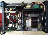
Here's a Pic of the inside of my 4024, for anyone curious.
samlex-4024-top-view.jpg
 
After pricing things out, I'm leaning heavily towards the Samlex combo. I can get it all done for less, because it's possible to buy really low quality 24V inverters and chargers. But that's not really an apples-to-apples comparison.

Looks like you're really closing in. I'm curious what your component cost breakdown is so far on this iteration of your plan.
 
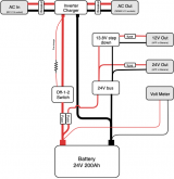
Updated diagram, everything in grey is something accessible outside the box, a socket, connector, display, etc.
24V power box v3.png

The list so far:
  • Battery: Specialized Power 24V 200Ah LiFePO4: $2459
    • I'm taking a chance here, I didn't feel like tackling building from cells. We'll see if it holds up once delivered.
  • Inverter/Charger:Victron MultiPlus 24/3000W 120V: $1,284
  • USB programming cable for inverter: $68
  • Battery terminal MRBF dual block plus fuses: $54
  • Blue Sea disconnect with Off/1/2/1+2 positions: $30
  • AC Breakers for In/Out: ~$45-60
  • Volt meter: Have several in parts bin: $0
  • Resistor for pre-charge: ~$5-10
  • Step-down regulator: TBD
    • Still shopping for this, going for ~20A. Daygreen has one on Amazon.
  • 24V Bus bar/fuse box: TBD
  • AC In/Out sockets: TBD
  • 12/24V Out connectors: TBD
    • Going have either banana binding posts, Anderson Power Poles, or both.
  • Cable + Ends: TBD
    • 2/0 for the battery/inverter connections, 8-12ga from my parts bin for the rest.
  • Box to put all this in: TBD
    • Thinking something like a Pelican 0550, but without the Pelican price and pick-n-pluck foam. Maybe a job site rolling box?
I'm working with forum Member Justin at Bay Marine on some of the items, so with the forum discount they offer, those will end up being cheaper than what I listed above.
 
Looks good.
I wonder, why 2 fuses from the batt bank ? Why not one fuse and split after that before that Blue Sea switch. I would also have a way to shutoff the 24v->12V side of it, for maintenance & repair works. My setup, I used a 24V-12V 20A Buck converter, fused with a 20A fuse from source, to a 12V toggle Switch so I can turn off the buck and everything beyond it. That saved me some hassles that could have been a problem. I used a good quality automotive toggle switch for that. I can access the fuse easily if need be and everything is kept safe & tidy.

Buck-Converter.jpg
 
Why? Because I overlooked that! Nice catch, thanks! :) I originally intended the disconnect as a total disconnect and your suggestion does that. As far as a switch for the 12V step down. I'm either going to leave out the separate switch, make it internal only for maintenance. In the scenarios I'm going to use this, disconnecting the whole battery to work on it is fine. Nothing critical needs to run from the 12 and 24V out. Those are there to support hobbies.

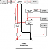
Here's the revised drawing:
24V power box v4.png

Hopefully it doesn't annoy others that this has become a build thread.
 
There ya go, now you got it nailed I think. I doubt anyone would complain about this becoming slightly more techy…. it's all learning stuff for others, which is a good thing.

I used a switch for the buck, because the buck 12V goes to power a USR RS485->Ethernet adapter, a RaspberryPi and supplement power to the little furnace heating the Powerhouse/Pumphouse, if the furnace's dedicated 12V battery get's too low.
 
UPDATE:
1) Dropped the 12V output.
2) Victron MultiPlus 24V 3000VA arrived and tested


I thought I'd give some quick updates
1) I decide not to worry about the dedicated 12V step-down regulator and output. If I want to add it later, I always can. I'll have just battery voltage on some panel mount APP plugs.

2) Thanks to @Justin Laureltec at Bay Marine for advice and helping me pick out the major components. I ordered a 24V battery from somewhere else and it hasn't shown up yet, but I did get the Victron MultiPlus inverter charger and wanted to test it. I thought others my find something useful (or maybe at least laugh) in how I hacked it together.

WARNING: This is all pretty hacked together and isn't the "right" way to do things, but it did work with gear I had on hand and it's intended only for testing while I wait for the rest of the parts. If you're not comfortable with how all these pieces fit together, don't do this.
.
Step 1 was to use the Victron software to upgrade the firmware and do the basic setup that I wanted. To do this, the Victron needs ~24VDC input. But...my battery isn't here yet. What to do? A cheap variable 0-30V bench PSU that I have for various projects. If you do this you MUST be sure the inverter/charger won't try and "charge" the PSU. To ensure this, I didn't plug in an AC input. I used a 20 Ohm resistor to pre-charge, and the ammeter on the PSU showed the current spiking and then quickly going down over about 6-7 seconds. Once I had everything configured for the LFE I ordered, I could test the low-voltage alarm and inverter shutdown by adjusting the voltage down.

Step 2 was to test AC pass thru, DC charging and the inverter from battery. So...I need an actual battery. As it turns out, I had a small 20Ah "battery bank" that were a bunch of old 6S LiPo batteries I used to use in some R/C helicopters. This was a set of 6S batteries ranging from 3.3Ah - 4.0Ah. All 6S (LiPos are 3.7V-4.2V so 6S is 22.2V - 25.2V). I already had these tied together in parallel, total capacity is a little over 22Ah. These LiPos got taken out of the rotation because they won't hold up to their original 25-50C discharge rates, but they do 5C just fine, that would give 22A x 5C = 110A of DC, more than enough for a test.

So, I saved the previous LFE-focused settings in Victron's VEConfig software and set different charge and inverter settings that are appropriate for the LiPo batts. I saved these in a different file. I had banana jacks wired up on the LiPo pack already, so I made a 10AWG banana plug to ring terminal cable so I could easily connect it to the MultiPlus.

For AC input and output, I cut an old extension 14AWG cord, I ended up with two 3ft ends, one ending in a plug the other ending in a socket. I fed them thru the cable glands on the Victron, stripped the ends and wired them into the AC in and AC out terminals. What I ended up with was a hardwired plug for AC in, a hardwired "socket" for AC out, and a set of female banana connectors for the battery input.

The test:
I plugged a battery monitor into the balance leads of the 6S LiPo pack, I left it at 50% SOC, giving room to charge and discharge. First, plugin the battery, then plug in the USB-MK3, and bring up VEConfig so I can watch what the AC In, AC Out, and DC in are doing. Next, plug in the AC, watch the charge starting, check the LiPo battery monitor and VEConfig to see the charge happening. Finally, plug in a150W lamp (picked it wouldn't use more than 10A from the LiPo bank) into the AC out. Then a did a few cycles of unplugging and plugging the AC in, confirming the inverter kicked on as expected.

It was all hacked together, and not a setup I'm going to use permanently, but let me get familiar with the how the MultiPlus works!
 
Last edited:
UPDATE:
1) 24V 200Ah battery arrived, some quick testing on it here: https://diysolarforum.com/threads/2846/
2) Change of plans on the container

I decided to keep the battery separate from all the gear. This will make getting into and out of a car easier, generally easier to move around. My plan is to have all the gear except the battery inside a box, with all the user-facing bits (AC in, AC out, big disconnect switch, etc) panel mounted to the box from the inside. I'll then connect the box to the battery using a set of SB175 2/0 connectors (it's a sort of new connector from Anderson, it's the length of an SB175 housing, but built for 2/0 cables and contacts, it mates with other SB175 connectors).

When moving the house around, I'll have something like a cart or dolly (battery on bottom, box-o-gear on top, strapped in). But if I want to take it someplace, I'll disconnect and can put the battery and the box in the car separately. Note that my setup is temporarily hacked together for bench testing only. I do have a fuse on the battery terminal, but when I build this for real, I need fuses on the AC input and the AC outputs.

wired and ready for test.jpg
 
Back
Top