diy solar

diy solar

Advice on DC to DC wire run for popup camper and Renogy DCC50S

brooke_heaton

New Member
Joined
Sep 28, 2020
Messages
31
Hi all, I have a 15 ft vehicle towing a 15 ft trailer - likely 34 ft total with the tongue but I'm calculating 40 ft since it has to run around a few things. The batteries are in the rear of the popup. I have the Renogy DCC50S 12V 50A DC Board Battery Charger with MPPT which can charge while towing and I'm wanting to add a wire run from my starter battery to two Valence U27s in the rear of the camper. Since the wire needs to run 50 Amps over that distance, I've calculated a voltage drop of 8.88 %, 50 amps, and a final voltage of 12.76 at the charger if using 4 AWG which seems fine. The drop is 14% if using 6 AWG, which would be an easier fit.
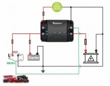
renogyDCC.jpg
I'm looking at using TEMCo 6 AWG welding wire which is rated for 115 Max Amps (up to 50 feet), 600 volts, -50°C to +105°C (-58°F to +221°F). I don't quite understand this rating. The 4 AWG is rated at 150 Max Amps (up to 50 feet), 600 volts, -50°C to +105°C (-58°F to +221°F). The information mentions nothing about voltage, so I'm confused about how it's simply rated for Amps. I'm basically balancing voltage loss versus getting this wire fed through the car's firewall, through the interior, out the back in through the camper. Cost isn't so much the issue as ease of installation.
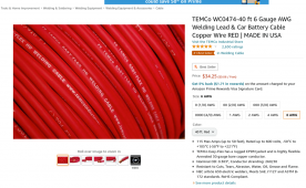
TEMCo WC0474-40 ft 6 Gauge AWG Welding Lead   Car Battery Cable Copper Wire RED   MADE IN USA ...png


Anyway is this wire something that is MORE performative than regular wire?. Would I be safe with 6 AWG? Or do I need to go with 4 AWG here?
 
Does your trailer use a 7pin connector? Instead of feeding all the way from your starter battery, can you tap into the 12v rail of the 7pin? If not, why not just keep the wire outside the cabin along the frame through a wire loom instead of routing through the firewall/interior?

Also, both the 4 and 6 AWG cables note that they're rated for up to 600 volts, so not sure what you mean that the information mentions nothing about voltage, could you please clarify?
 
Last edited:
@F1uxCapacitor The 7-pin 12-volt line maxes out around 2 Amps which can only feed ~30 watts. I tried that and it's a non-starter. I definitely want to get the full 50 Amps/600 watts pushed to the RV batteries. When I tried using the 7-pin last weekend, it was a disaster and could hardly keep enough energy to run the fan :( I have a cooler and a few other demanding things that I'd want to keep charged. So, unfortunately, this will require a much thicker gauge wire run from the TV Battery to the RV Battery bank.
 
Makes sense. Are you just running from your starter battery, or are you adding any PV panels? I ask because the Renogy site states that the DCC50S only provides 25A charge current from the starter battery/alternator, and 25A from PV panels.

Where are you planning on placing the DCC50S? Within your tow vehicle, or within your trailer?
 
@F1uxCapacitor I have 2 100 watt folding panels that I've been using as well and may add some flexible solar panels to the top of the camper to charge via solar while driving. But there will be times when there's no solar charging so it can do the full 50 Amp via the TV if no solar charging is happening (from what I understand).

Will Prowse got 51 Amps via the alternator input alone:

The DCC50S is currently placed right next to the RV batteries with about a 15 inch run between them.
 
Is there a reason you're wanting to run the cable through the interior of your TV cabin vs keeping it outside along the frame?
 
This kit is actually 25amps of charge from the alternator + 25 amps of PV charge = 50 amps. Kind of misleading. I did not watch the video that claims 51 amps. Based off the specifications from Renogy, I’d calculate a 25 amp, not 50 amp for voltage drop.

If I were to run wire along a frame. I would wrap it in split loom. I also don’t like external wiring that can get torn at by brush as I drive across the road.
 
That's a fair question. Ultimately I just don't want a capable carrying a high amperage outside the car and exposed to the elements on the undercarriage of a car. I also don't want it exposed to that much heat if available. It may be possible to do it, but it's not my top choice.
 
@chrisski check out the video. The performance is demonstrated live. It can charge at 50 Amps IF there's no solar charging. That's what it seems to show pretty clearly. The documentation and information are unclear, for sure. In the case that it IS maxed at 25 Amps, that would incentivize reducing the gauge of the wiring for ease of use.

The top review on the Renogy site notes this behavior - 100% alternator charging up to 50Amps if no solar. 50% alternator and 50% solar if both.

 
Last edited:
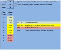
I don't think 6 awg is going to cut it. That 34' distance is 68' of round trip. 50 amps of output from the charger likely requires more than 50 amps of input. Going on those revised assumptions, I plugged the numbers into the calculator linked below.

Capture.JPG

Even if you get only 25 amps of output (call it 30 amps input), 6 awg still isn't going to cut it.

 
Thanks. Renogy is not the best at customer service and has some errors in documentation or specs. I got my specs here: https://www.renogy.com/dcc50s-12v-50a-dc-dc-on-board-battery-charger-with-mppt/.

By all means, if this pushes 50 amps, that’s what the wiring needs to do. I just wish the manufacter’s page made it a little clear than


Maximum Charging Current : 50A (25A Alternator / 25A PV)
 
While I definitely understand not wanting to expose conductors to the elements, it's my personal opinion that that much ampacity should remain outside the firewall/interior for safety reasons and, in your situation, simplicity of installation. You can always wrap in split loom as @chrisski suggested, and even tuck it up and secure it in a less exposed area.

To me it's the same reasoning behind using 4/5 pin relays w/ switches inside the vehicle... keep the high amps out, low amps in. Again, personal opinion, I'm just here to ask questions, bounce ideas around, and see what sticks!

Speaking of ideas, not sure if you have your disconnect between your TV and RV figured out, but with that much ampacity and size cabling, look into Anderson Connectors.
 
@HRTKD I'm open to adjusting this. @Will Prowse suggests using the common ground, tied to the chassis, which is how mine is already wired for the solar. He also suggests the 4 AWG but perhaps that assumes a shorter run.


Perhaps I'm not understanding what I should be doing with this setup.
 
The resistance of copper and the resistance of steel are different. The calculators assume you're using good quality copper. When I've run lines for winches to the back of a truck, both positive and negative cables are run. Those cables support usually at least twice the amps you're using, so it's not quite an apples-to-apples comparison.

My approach is, you're running one cable, why not run two? It's the expense of two lines, not the labor of running two lines that is the limiting factor. And I agree with F1uxCapacitor on running the cables on the exterior of the vehicle.

The cabling issue is one of the reasons I'm not a fan of charging trailer LiFePO4 batteries from an alternator. I don't use the alternator charge at all in my trailer. But I have solar on top to provide power.

On a positive note, I've had great experience with TEMCo cable and their associated supplies.
 
@Will Prowse suggests using the common ground, tied to the chassis, which is how mine is already wired for the solar. He also suggests the 4 AWG but perhaps that assumes a shorter run.
THere’s a few things I’ve seen people do, that I would not do.

A common ground with a frame for a 50 amp circuit is one of them. I am not an electrician, but I take things from my electronics technicians background and Google sources and it’s usually a big no-no to use high amperage common ground. Also, all the large amperage devices that were in the circuits I fixed had it’s own grounding wire, and not a common ground.

The other thing is some of the recommendations for wire sizing seem a little thin. I made an 8’ run for a 50 amp cable, and I came out to 2 AWG. I had extended a 18” run that was 6 AWG wire for the same amperage. So distance makes a huge difference when it comes to low voltage DC and amperage and volt loss. That 18” run with 6 AWG was fine for such a short distance, but not the 8’ I moved the equipment to.

I am ultra conservative when putting together my systems. As an example, For a 12 volt inverter for 2000 watts with 6’ runs to the battery, I use 4/0 copper wire, which some will scoff at saying its ridiculously wasteful.
 
The 4 AWG is rated at 150 Max Amps (up to 50 feet), 600 volts, -50°C to +105°C (-58°F to +221°F). The information mentions nothing about voltage, so I'm confused about how it's simply rated for Amps.

I'll take a stab at this. The specs do mention voltage. It's 600 volts! The more volts on the wire, the easier the amps flow through. So the higher the voltage the more amps are allowed. Conversely, if you're only dealing with 12 volts, the amps can't be very high.

Whenever you're sizing wire, you have to know at least three things: volts, amps, distance. The rules/formula get complicated when we have to consider the insulation on the wire and if the wire is in conduit. I can't explain those two factor with any authority.
 
Back
Top