diy solar

diy solar

Advice on land mounted array 60 m (200 ft) away from the solar charge controller

tomashubelbauer

New Member
Joined
Nov 12, 2022
Messages
26
Location
Prague
Hi, I have a barn where I have run a small solar system I use to power its lights as well as the occasional power tool. There is a semi-insulated brick room in the barn so I can keep the electronics (solar charge controller, invertor, batteries with internal heaters) there. The barn has a south facing wall which I am currently using to mount the panels but I am running out of unshaded space of this wall. I don't want to fell the tree that shades the rest of the wall so I am thinking about moving my solar array and mounting it on my land.

The spot I have in mind is around 60 or 70 meters away from the barn. That's approximately 200 or 230 ft. It is the closest sunny spot to the barn, other spots are partially shaded by trees.

I am seeking advice on whether it would be better to move the electronics and the batteries also and build an insulated shed where to place it all and then just bury an AC line to the barn or whether it makes more sense to run a DC line from the panel array to my barn and size the array such that I negate the resulting voltage loss. I am in Europe so the AC line would be 230 V if I did build that shed next to the array itself.

Right now I am using 4 175 Wp 20 V panels in series but I am hoping to grow the array in the future. Perhaps it makes sense to run DC now but for 4x the array you'd suggest AC instead? Or would the voltage drop be too much and I should go straight with AC? Something else?

Has anyone dealt with a decision like this and can you share your experience?
 
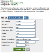
To me its just a math problem, and this is the calculator I’d use:


My guess without doing the math is to go with DC in all cases from the panels to The barn. DC tends to be much more forgiving of voltage Torrance wise than AC When you look at voltage inputs. 120 VAC equipment tends to be a rather narrow voltage spec, perhaps 115 to 125 depending on the item, whereas the DC you’re sending to the MPPT SCC several hundred feet away could have a voltage tolerance of 100 VDC or more.
 
So for my current 4 175 Wp panels with 18.3 V and 9.56 A (under load) connected in series, so 73.2 V and 9.56 A or 700 Wp if I ran a 70 m (230 ft) length of 10 AWG (6 mm2) copper cable I am looking at a 7.13 % voltage drop, so 67.98 V on the other end going to the SCC. That's 650 Wp.

And if I wanted to improve that, I'd use 8 AWG or lower.

So the optimization problem here becomes finding the optimum between adding more panels to offset the loss or buying thicker wire to lower the loss, whichever works out better financially. And when it comes to scaling up, more variables are whether it is better to buy a better SCC that can handle more voltage or add another run(s) of wire and have two or more strings.

Did I get this right? Thanks a lot for the answer.
 
And if I wanted to improve that, I'd use 8 AWG or lower.
Yes, but joining a MC4 connector to a thicker than 10 AWG wire is difficult.

I did this by folding over the cable at the end of the 10 AWG portion which made this 6 AWG, and butt crimped to a 6 AWG cable. Keep in mind this made the numbers on the calculator do wicked good, but there is some loss at the butt splice I can’t measure. That cable and 900 watt portable angled array produces more power than my 1650 watts of fixed flat panels, so that is what is important.
So the optimization problem here becomes finding the optimum between adding more panels to offset the loss or buying thicker wire to lower the loss, whichever works out better financially. And when it comes to scaling up, more variables are whether it is better to buy a better SCC that can handle more voltage or add another run(s) of wire and have two or more strings.
Yes.

The voltage loss prior to the SCC is not as important as the voltage loss after. Is it really that big of a deal that your panels are losing 7%? If it takes 4 good hours of charging to top your batteries, that may be an extra 30 minutes. I did not always think that way. I used to shoot for less than 3% loss over any run.

Post SCC voltage loss is important. You want your SCC out voltage to be pretty close to your battery voltage. For the few builds I’ve done SCC and battery are close enough to each other this does not matter, but battery voltage and SCC out voltage could be a tenth or a so volt off.

Also with this, remember the record cold temp adjustment to account for higher voltage on cold days.
 
Good point about the MC4s! I think I will go with 10 AWG and accept the voltage loss. Maybe I will upgrade to higher Wp panels so that the output voltage of the array is higher and it is still high enough even after the loss. I will keep the temp adjustment in mind, thank you. I am using a 12 V battery now but I am thinking of switching to a 48 V system so I think I just need to make sure I have at least 48+5 V at the SCC input so I will shoot for 60 V with the calculator as I figure out the parts. The loss at the output of the SCC is super minimal, I have it practically right next to the battery on a meter long cables, with just enough space between the batteries and the SCS for the SCC to have room for cooling airflow around it.
 
Good point about the MC4s! I think I will go with 10 AWG and accept the voltage loss. Maybe I will upgrade to higher Wp panels so that the output voltage of the array is higher and it is still high enough even after the loss. I will keep the temp adjustment in mind, thank you. I am using a 12 V battery now but I am thinking of switching to a 48 V system so I think I just need to make sure I have at least 48+5 V at the SCC input so I will shoot for 60 V with the calculator as I figure out the parts. The loss at the output of the SCC is super minimal, I have it practically right next to the battery on a meter long cables, with just enough space between the batteries and the SCS for the SCC to have room for cooling airflow around it.
I'm just curious how you will run the line from the SCC. Buried, Conduit, etc...?
 
The solar panel array will be land mounted and the line from it to the SCC input will be in a conduit and buried. The line from the SCC output to the battery is just wall mounted, the SCC and the batteries are in the same spot in the shed.
 
Right now, I've got an array 130' away from my combiner box, and I'm looking at no significant voltage drop using 10 gauge wire. Looking at your situation, wiring four 30V grid-tie like mine in series to give you 120VDC would result in only about 3% voltage drop at 200 feet. That would go down to only 2% loss if you bumped up to five panels and utilized a 250Voc limit controller.

1670172712139.png
 
Possibly the easiest cheapest way will be to replace the 4 panels with higher output units. How much extra do you need ?
 
Yeah I am definitely going to be looking at replacing the panels. The ones I have currently aren't able to top up the batteries as fast as I'd like. With the new spot and better panels I am positive I should see much better charge times as I will be able to both catch and convert more light.
 
Hi, your solar array needs to be high voltage with high voltage charge controller so a 12 volt system with 12 volt solar panels will not work well over a long distance and generate high amps so thick wiring would be required with maximum 25 amps at mc4 connectors. If you are going to upgrade your solar system a 48 volt 500volt dc to ac hybrid batteryless unit converting dc direct to ac would be best requiring a smaller battery bank.
 
The solar panel array will be land mounted and the line from it to the SCC input will be in a conduit and buried. The line from the SCC output to the battery is just wall mounted, the SCC and the batteries are in the same spot in the shed.
While your at it, and I did the same, add extra wire in that conduit for expansion later. If you think you will expand. I was glad I did it.
 
Back
Top