diy solar

diy solar

Advice on LV6548 w/ 20 Panel Array

bryanxwhite

New Member
Joined
Mar 22, 2022
Messages
11
I've spent a lot of time on the forum reading and I think I'm asking the right questions. I've answered a number of my questions searching the forum but there's still a few I'm unclear on.

I have a single LV6548 w/ a 48v forklift battery (12-125-17 x2 - 1,000ah). I've got 20 260w used panels from SanTan.
VOC: 38.2
Pmax: 30.6
Amps: 8.5

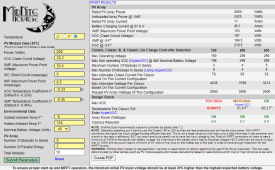
Based on Midnite's calculator & the lowest temp for where I live, I can run 5s4p to stay under the 250v max on the coldest day. Since there are 2 PV inputs on the LV6548, do I need to have 2 combiner boxes with 5s2p each? This is the screenshot from the Midnite website. I would need to have 2 runs of PV input going from the array to the MPP, right? Or can I run 5s4p to a single combiner box and have a single PV run back to the MPP?

1649787686161.png
 
If anyone can point me in the direction of a similar thread, it would be appreciated. I couldn’t find one close enough searching.
 
you just need a Y connector to connect 2 strings of 5 panels to each other then make 2 wire runs to the inverter, dont need a combiner box.
i am also using 250 watt panels and lv6548. using a 6s2p to each input on the inverter thats 24 panels at 6kw total.
 
you just need a Y connector to connect 2 strings of 5 panels to each other then make 2 wire runs to the inverter, dont need a combiner box.
i am also using 250 watt panels and lv6548. using a 6s2p to each input on the inverter thats 24 panels at 6kw total.
What are you using for a solar panel disconnect? Are you using inline fuses?
Really appreciate the info!
 
I have a Midnight combiner, and it can be configured for two positive inputs independent of each other. If you look at the drawing below, you can see the breaker bus at the top of the combiner has a notch halfway across the top. This is so the bus can be cut in half to create two different positive outputs. So, in cutting completely through the bus to make it two separate pieces, breakers 1-3 could be wired for + output #1, attached to the left-hand screw-terminal, and breakers 4-6 could be wired for +output #2, attached to the right-hand screw-terminal.
1649944840747.png
 
I have a Midnight combiner, and it can be configured for two positive inputs independent of each other. If you look at the drawing below, you can see the breaker bus at the top of the combiner has a notch halfway across the top. This is so the bus can be cut in half to create two different positive outputs. So, in cutting completely through the bus to make it two separate pieces, breakers 1-3 could be wired for + output #1, attached to the left-hand screw-terminal, and breakers 4-6 could be wired for +output #2, attached to the right-hand screw-terminal.
View attachment 91201
Thank you for the diagram! I didn't know that was possible. I think this is the route I'll go as it will double as a PV disconnect.
 
Back
Top