diy solar

diy solar

AIO Bonding

LSC

New Member
Joined
Apr 14, 2022
Messages
141
I have read several posts on this subject. I get mixed answers as to what to do with the bond issue. I have an AIO that when you do a continuity test between the AC IN G & N you get no connection, No Bond. There is a connection between the AC IN G and the AIO case G. That's Okay I believe.

So do we bond the AC IN N & G at the AC OUT Breaker Box or Not?
 
The only place to make the G-N bond is at the main panel.

How that is handled when in invert mode depends on the unit. My Outback has grid neutral in, gen neutral in, and neutral out, but they're actually all tied together so when in invert mode the main panel G-N bond is still active and functional. Some units switch the N, in which case they should also switch on a G-N bond when in invert mode. Some don't do this, or some don't even use a neutral in from the grid, which is really bizarre and troubling to me. I've seen where the neutral from grid is still tied to the loads panel directly though, and the inverter neutral ties to it, so they are still all interconnected and therefore the G-N bond at the main panel is still active. I dunno. Some documentation of some inverters is confusing or lacking.
Yes, confusing. I have a breaker box for the AC OUT and it has a bus bar inside. That is where I am wondering if it is the place to do the bond or not?

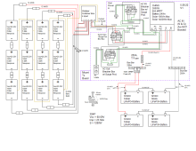
Here is the circuit. With all these dang grounds I hope there is not a ground loop in there somewhere.
 

Attachments

  • 100W AIO 3S4P V1.png
    100W AIO 3S4P V1.png
    53.9 KB · Views: 11
AIO make & model?
What does the manufacturer recommend?

Lots of folks say there is only one place to bond Neutral and Ground. (y)
 
AIO make & model?
What does the manufacturer recommend?

Lots of folks say there is only one place to bond Neutral and Ground. (y)
CHINS 3000W. I have read over the manual and it is not mentioned. I will need to contact them. Thanks
 
I am not savvy enuff to answer your question, but I have a similiar question. I have a subpanel in my closet that is fed 240v from the main. I want to put an EG4 3kw inverter and a battery pack in there. I'm going to put a 125amp load center next to the existing panel and move six 120v circuits into it. And then put a 60 amp breaker into the original subpanel and feed it into the inverter. The manual says that the load box should have separate busbars for the G and N lines. My question is, should the feed panel also have separate busbars for G and N? It does not now.
 
Your main panel has the G-N bond. Sometimes this means one bus bar that both G and N wires connect to, sometimes there are separate bus bars but they're tied together with a bond screw. Depends on locality rules at the time the house was built.

However, EVERY panel after that should have separate bus bars for G and N to keep them separate. If your existing sub panel in your closet does not, then it is wired how the sub panel in my parents' old house was wired - incorrectly.
 
Normal house outlet.
In that case, your AC Input should be providing the N-G Bond from your main service panel.

What you have to figure out is how does your AIO handle the N-G bond when inverting from battery (don't necessarily trust what support tells you either. MPP gave me the wrong answer regarding my 1012LV-MS).

And then knowing that answer, influences what you should (or should not) do on the output side of things.

Remember... ONLY 1 N-G bond. Having it in 2 places can be dangerous.
 
Your main panel has the G-N bond. Sometimes this means one bus bar that both G and N wires connect to, sometimes there are separate bus bars but they're tied together with a bond screw. Depends on locality rules at the time the house was built.

However, EVERY panel after that should have separate bus bars for G and N to keep them separate. If your existing sub panel in your closet does not, then it is wired how the sub panel in my parents' old house was wired - incorrectly.
Thanks for clarifying that. I will have to add a ground busbar to that panel also, and should it be bonded to the metal box or insulated from the box.
 
Ground bus bar can be bonded to the metal box. It should be grounded. The Neutral bus bar should be isolated from the metal box.
 
That leads me to my next question. Can I use the ground wire from the inverter out wire as a ground for the load panel or should it have a separate earth ground? seems like I might be creating a ground loop if I use the inverter ground wire.
 
What you have to figure out is how does your AIO handle the N-G bond when inverting from battery
That is a question I have sent to them. I will have to respond back when they answer. Thanks
 
That leads me to my next question. Can I use the ground wire from the inverter out wire as a ground for the load panel or should it have a separate earth ground? seems like I might be creating a ground loop if I use the inverter ground wire.
All your grounds should connect together. The load panel should have a ground connection back to the main panel's ground that contains the connectionto the earth ground. The AIO ground gets connected to the same ground system. No separate grounds.
 
All your grounds should connect together. The load panel should have a ground connection back to the main panel's ground that contains the connectionto the earth ground. The AIO ground gets connected to the same ground system. No separate grounds.
Just checking, so I don't get lost.

"No separate grounds" means "stick one ground rod in the ground". Yes or No?
 
Just checking, so I don't get lost.

"No separate grounds" means "stick one ground rod in the ground". Yes or No?
Yeah I'm assuming his main panel already has that done. Do not add another one at another location, do not ground the inverter separately from the rest of the system, do not ground the inverter and load panel separately from the rest of the house. It should all tie together, back to the main panel, which is earth grounded already (the sole location for an earth ground).
 
If you are using an off grid system like in post #3 and you are not connecting to the grid, via a transfer switch, but you do connect to the house AC power to help charge the batteries if needed, then how is the grounding, in this type of system, supposed to be done? There is no affiliation to the houses panel or it's ground.
 
How you have it shown would connect it to the house ground when plugged in to the house power. When it isn't plugged in, your ground is floating, so you would want to tie it to a ground somehow (clamp to a grounded rod, or to a house ground, or something).
 
so you would want to tie it to a ground somehow (clamp to a grounded rod, or to a house ground, or something).
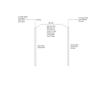
So if I wanted to ground the solar panels but not tie them to the solar system ground inside I could maybe do what's in the pic. This would create an under ground way to dissipate the surge. Kind of an underground loop until it is dissipated.

If I leave the inside solar system tied to each other and to the AC IN ground (and leave it plugged in) then I have it grounded but not to rod ground. No surge gets in. Maybe?
 

Attachments

  • Ground Rods.png
    Ground Rods.png
    14.9 KB · Views: 9
Back
Top