I can answer some questions about how the Growatt handles ground and neutral bonding. Short version: it doesn't.
Long version: I have the 3000w Growatt (SPF 3000TL LVM-48P) and have stumbled upon some neutral and ground issues while testing mine. I'm just going to brain dump my observations and measurements:
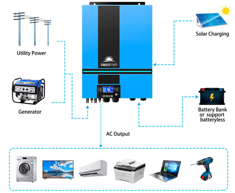
1. The ground terminals of AC input and AC output are connected (bonded) to each other and the metal chassis at all times. This is true even with the Growatt completely unpowered and disconnected.
2. The neutral terminals of the AC input and AC output are never connected (bonded), regardless of connections, operation mode, and settings.
3. The AC output neutral and AC output ground are never bonded internally by the Growatt. When AC input is grid connected
and running in bypass mode, the AC output neutral and ground are technically bonded, because they are bonded at the utility service panel. In any mode where the inverter is powering the load, neutral is not bonded to ground.
4. The dry contacts (and associated setting 24) can be utilized to trigger an external grounding box - basically, a relay switch that bonds ground and neutral. The manual is extremely vague about this.
5. Unless you have externally bonded AC output neutral to ground, the neutral line will have a floating voltage ~60V N-G. (H-G = 60V, H-N = 120V)
As I understand it (disclaimer: I am not an electrician) the US NEC requires that neutral and ground are bonded only at the first service panel. I know these Growatt (and similar - MPPT, etc) are marketed as "Off Grid" even though utility charging/bypass is a prominent feature, but that leaves you to figure out bonding.
Practically speaking - if you are going to use the inverter as portable (like that hand truck I saw posted) then it is not going to be properly grounded anyway. If this is going into a dwelling where it will run unattended, then there are some safety issues that should be addressed first.
Are you using one of those 3-neon bulb circuit testers? The result was ambiguous on mine - one of the bulbs was half-bright because of the floating neutral. A voltage meter was much more useful for verification.
Here is what I did temporarily while troubleshooting. First, I tested the outlet supplying grid power to the Growatt input. Make certain it has a good ground, and no voltage between neutral and ground pins. If that is good, then fully shut down and disconnect the Growatt inverter. Using a short piece of insulated wire, connect N terminals of AC input and output together. Then reconnect everything else and retest. Don't worry about setting 24 for this test. If the problem goes away while the AC input is connected to a good grid-fed receptacle (even when running on inverter mode) then the missing neutral-ground bond is the root cause. Only attempt this if you understand and are comfortable doing this test yourself. Also, don't use this as a permanent solution.


")