diy solar

diy solar

Alternator Charge Wiring

caymaanedge

New Member
Joined
Jul 19, 2020
Messages
124
Trying to figure out how to manage lithium with alternator.
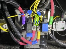

Here's my setup
680ah LifePO4 Coach Batteries
2 - 100ah AGM Chassis Batteries
1200 watts solar charging Coach Batteries
100 watt solar charging Chassis Batteries
8kw Generator Charging both Chassis/Coach Batteries
Engine Alternator Charging both Chassis.Coach Batteries


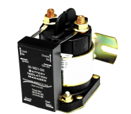
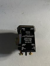
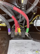
Currently managed with Precision Circuits Battery Isolation Manager


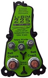
So I would like to just disconnect the Alternator charging of the Coach Batteries, or manage their charge demand somehow. I know there is a Li-BIM and Victron DC-DC charger, but I'm not sure how to use either of those with the current Precision Circuits BIM. The current set-up manages the generator charge for both banks and allows for bridging the two banks together with a dash switch if needed.


Anyone gone down this path?
 

Attachments

  • Precision Circtuits BIM.png
    Precision Circtuits BIM.png
    331.6 KB · Views: 5
  • Li BIM.jpg
    Li BIM.jpg
    14.3 KB · Views: 5
Buy a proper B2B. I suggest Sterling Power as they make a variety of options depending on starter/house voltages.

The LI-BIM will work but it is not optimal; you are better off spending a bit more on a B2B.

If you specify:

Starter battery voltage -- assume 12V
House battery voltage -- assume 24V
Alternator voltage and amperage output

I can send some links.
 
Thanks for the input.
Do I need to remove the Precision unit or does the DC-Dc just jumper between the alternator and battery banks?
 
  • Like
Reactions: JMc
Thanks for the input.
Do I need to remove the Precision unit or does the DC-Dc just jumper between the alternator and battery banks?

The B2B will have a "starter" power input, and a "house" output. It doesn't need anything else except a ground.

Some might want an ignition signal to know when to run instead of using voltage levels due to some of the newer EURO5 and EURO6 standards requiring engine shutoff at idle and all that emissions stuff. But most RV's don't have these systems yet - except newer Sprinter and Transit based units.
 
allows for bridging the two banks together with a dash switch if needed.
This is were I am at too. I want to retain the "Battery Boost" switch to jump start the chassis battery from the house battery using the battery isolation relay.

My MH uses this device to control the isolation relay. Maybe I can disconnect the blue wire to disable it.
 
Ok so I made progress but ran in to an issue. I pulled out the Precision BIM and installed the Li-BIM after building mounting plate and getting enough slack. Not thrilled with the proximity of the chassis/coach battery leads...

Here’s how the small gauge wires are connected.
Ignition-Ignition
Ground-Ground
Dash Switch-Signal
GenSet-Capped Off

The coach powers works fine, 13.3v . Turns on with switch by door, powers everything and inverter works.

The Chassis power is dead. Incoming, pink lead, has 12.5v. Disconnect switch will not work and there is no power getting to purple lead to start coach.

ideas?
 

Attachments

  • B2501675-FC9E-4D56-B6AB-818F8D9A0C5B.jpeg
    B2501675-FC9E-4D56-B6AB-818F8D9A0C5B.jpeg
    86.8 KB · Views: 9
  • 53571164-079D-4F9C-B784-82007BEE8315.jpeg
    53571164-079D-4F9C-B784-82007BEE8315.jpeg
    360.7 KB · Views: 10
  • 0AF1A562-3BD6-4E1A-A956-3EC5D3615492.jpeg
    0AF1A562-3BD6-4E1A-A956-3EC5D3615492.jpeg
    214.7 KB · Views: 9
Last edited:
More...I pulled the ignition and signal connections off the Li-BIM. Power now flows through the disconnect switch to the chassis side and everything works. The Ignition lead does get 12.5v when the ignition switch is on, but is dead when ignition is off.

So....
 
Last edited:
Back
Top