Hey guys,
So I'm trying to finalize my electrical system and determine what wire gauge is necessary for certain runs.
It's my understanding that I need to take into account voltage drop AND ampacity. I understand the voltage drop and have been using the calculators, but I'm a bit confused with ampacity.
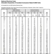
I've seen the NEC ampacity chart posted in other threads, which shows the ampacity of a 2/0 conductor as 195A for a 90 degree C rating.

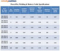
At the same time, there are ampacity tables for welding cable that give different values for max amperage. For example, this page shows 325A max for 2/0 cable: https://temcoindustrial.com/product-guides/wire-cable-and-accessories/welding-cable
The other place I've been looking is the Blue Sea Chart, which I understand is for determining the wire gauge needed to stay under a certain voltage drop, but why would it even show 2/0 cable as an option in the 200A column if the ampacity is, in fact, 195A?
Specific to my application, I have three 12V, 100ah lithium batteries wired in parallel, as well as a 2000W inverter. I was planning to use 2/0 cable to connect the batteries to each other, connect the batteries to the bus bars, and to connect the inverter to the bus bars. I had also planned a 250A fuse for the inverter to bus bar positive wire and a 300A fuse for the battery to bus bar wire. Now I'm second guessing if 2/0 is the correct choice.
I've seen other wiring diagrams posted that use 2/0 cable for similar sized battery banks and 2000W inverters: https://www.explorist.life/2000w-520w-60a-budget-friendly-camper-wiring-diagram/
What am I missing here?
So I'm trying to finalize my electrical system and determine what wire gauge is necessary for certain runs.
It's my understanding that I need to take into account voltage drop AND ampacity. I understand the voltage drop and have been using the calculators, but I'm a bit confused with ampacity.
I've seen the NEC ampacity chart posted in other threads, which shows the ampacity of a 2/0 conductor as 195A for a 90 degree C rating.

At the same time, there are ampacity tables for welding cable that give different values for max amperage. For example, this page shows 325A max for 2/0 cable: https://temcoindustrial.com/product-guides/wire-cable-and-accessories/welding-cable
The other place I've been looking is the Blue Sea Chart, which I understand is for determining the wire gauge needed to stay under a certain voltage drop, but why would it even show 2/0 cable as an option in the 200A column if the ampacity is, in fact, 195A?
Specific to my application, I have three 12V, 100ah lithium batteries wired in parallel, as well as a 2000W inverter. I was planning to use 2/0 cable to connect the batteries to each other, connect the batteries to the bus bars, and to connect the inverter to the bus bars. I had also planned a 250A fuse for the inverter to bus bar positive wire and a 300A fuse for the battery to bus bar wire. Now I'm second guessing if 2/0 is the correct choice.
I've seen other wiring diagrams posted that use 2/0 cable for similar sized battery banks and 2000W inverters: https://www.explorist.life/2000w-520w-60a-budget-friendly-camper-wiring-diagram/
What am I missing here?


