diy solar

diy solar

AMPINVT 24v/3000w Inverter/Chargers

TLDR: AMPINVT inverter charger is just a dumb power supply :(. It does not have three stage charging like all the sigineer rebrands - maybe its made by another OEM?

After no email response from AMPINVT customer support, I finally got someone to respond...on whatsapp...

Yesterday he said the inverter charger is 3 stage charger, but was unable to tell me when absorption/bulk charging ends (time? current?), and what the float voltage is for each battery type (SLA, AGM, Gel). He just sent me a notional 3 stage charge plot of voltage & current. useless
He claimed if I set the custom/lithium charge voltage to 14.2V it would float at ~13.5V. That would be cool, right!?

Well I've had a lead acid at 14.2V for 24 hrs without seeing it drop to float. I sent a photo of the meter and explained this, and he came back saying basically, "only the MPPT controllers have multi-stage charging."

Well that's a bummer for charging LFP, but at least it corroborates what I'm seeing. It's just a dumb power supply.

I guess I can:
1) accept that I won't be able to charge quickly, set charge voltage to ~13.5V or 13.6V, and charge nearly full without risk of damage if I don't turn the charger off in time. This would take a really long time to charge a 560Ah bank (max charge current 35A, and most of the time would be spend in CV mode), but should get the bank mostly charged. I don't want to leave a backup battery sitting at 100% SOC anyways. Is there anything wrong with this method?
2) increase charge voltage if I need to charge quickly (i.e. manage the charge stages manually)

I wouldn't consider the above options if this system were to be used daily, but for occasional use maybe it's ok?

Or I can return it and spend more money to get full functionality...TBD

One other annoying feature is that the actual output voltage is 0.2V > the set voltage. I can work with that but it's annoying.
 
Every time I need to get InTouch with customer service I do it via Facebook messenger and they reply quite quickly.

I have had a 60a mppt charge controller of there's for a year now and have decided to keep it over the epever it's now replaced, performs much better in low light conditions
 
I just got mine up and running... currently on line priority because my solar panels are not installed. My friend accidentally tripped the breaker while running the A/C and microwave simultaneously. Other than that I have noticed no issues and I am pleased with the product. I can't wait to get the panels going.

View attachment 12118

is you AMPINVT inverter still up and going​

 
have decided to keep it over the epever it's now replaced, performs much better in low light conditions
Old thread…
Can you elaborate on that?

I have Epever AN50 that repeatedly cuts out on equalize mode so I’m disenchanted.

(I have lead acid batteries)

Ampinvt website shows a low-frequency hybrid for 12V-120VAC but I haven’t found a US-soil stocking distributor.
 
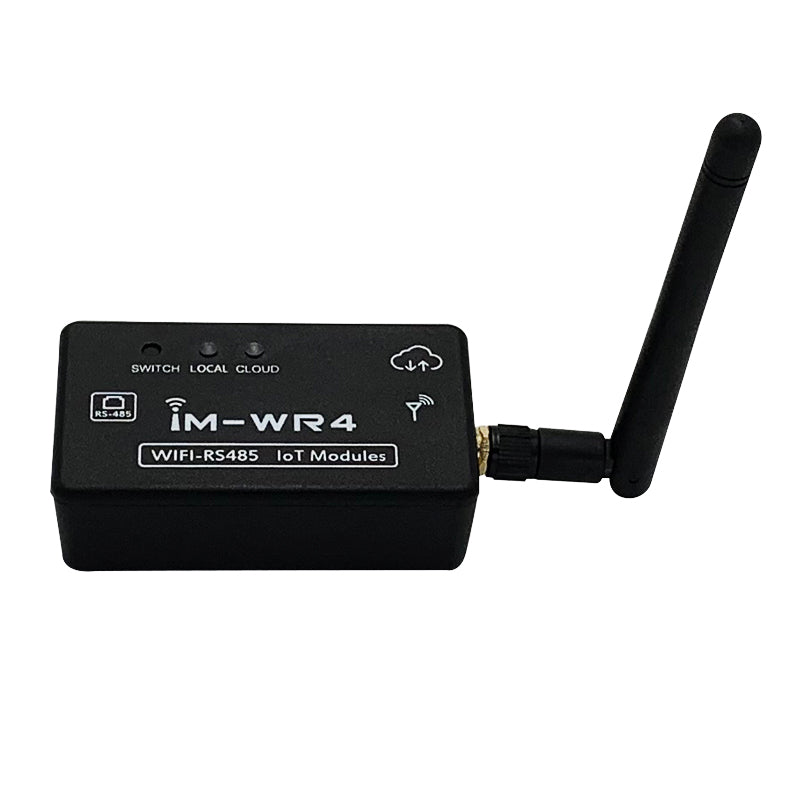
Looks like the suggested configuration is a WIFI-RS485 adapter and an android app?

Has anyone been able to get the RS485 to work? I have a similar MPPT charge controller from this company and for the life of me cannot get the serial connection to work at all. I have a serial port sniffer and been through hours of battle. The pinout of the rs485 ethernet port are the orange pair and the brown pair. No continuity on the green and blue pairs. Any input would be greatly appreciated.
 
Has anyone been able to get the RS485 to work? I have a similar MPPT charge controller from this company and for the life of me cannot get the serial connection to work at all. I have a serial port sniffer and been through hours of battle. The pinout of the rs485 ethernet port are the orange pair and the brown pair. No continuity on the green and blue pairs. Any input would be greatly appreciated.
Josh,

I've been trying to get this to work too. I found the user manual that confirms the brown wires are vcc & ground and the orange wires are the two data pins. It looks like it uses modbus so i attempted to read it using mbpoll in linux, but I didn't get anything. I contacted the company, and they gave me the communications document, but I've had no luck with that either. If I get it working I'll report back for sure.
 

Attachments

  • NEW MPPT communication protocol.pdf
    590.4 KB · Views: 60
  • En-manual.pdf
    2.6 MB · Views: 54
Josh,

I've been trying to get this to work too. I found the user manual that confirms the brown wires are vcc & ground and the orange wires are the two data pins. It looks like it uses modbus so i attempted to read it using mbpoll in linux, but I didn't get anything. I contacted the company, and they gave me the communications document, but I've had no luck with that either. If I get it working I'll report back for sure.
Hi steviep19, were you able to communicate with the unit via RS485? Did it work for you?
 
I found a project on github that does work with and ESP32: https://github.com/TripitakaBC/ampinvt_esphome

I was able to pull stats from the device and dump them into Home Assistant.
Hi steviep19. Again, thank you for the help. I cannot communicate with the device. Could you please confirm which RS485 connector wires you used for the communication with the charger? Based on the attached documentation these are 1 (B+) and 2 (A-). Have I gotten it correctly? Did you use the ground wire (pin #8) as well?
 
Hi steviep19. Again, thank you for the help. I cannot communicate with the device. Could you please confirm which RS485 connector wires you used for the communication with the charger? Based on the attached documentation these are 1 (B+) and 2 (A-). Have I gotten it correctly? Did you use the ground wire (pin #8) as well?
Ok, I was able to resolve the problem. I can now easily communicate with the charger. Thank you for the help.
 
Ok, I was able to resolve the problem. I can now easily communicate with the charger. Thank you for the help.
Hi Mr.VladG. I'm currently facing an issue. I've attempted to connect the MPPT Solar pins A B G to the converter pins 1 2 8 respectively. However, after sending data, I'm not receiving any feedback.
Do you have any suggestions? I'm using an ESP32 with an RS485 to TTL converter with Auto Flow control.
I didn't use 8 at all - not required. In addition, you have to wait for the response. The unit is fairly slow. Just wait for the response and you will get it. Plz refer to the method "execute" in the attached class. The code is not final, however, I constantly get the response from the charger.
 

Attachments

  • ampinvt.zip
    3 KB · Views: 11
I didn't use 8 at all - not required. In addition, you have to wait for the response. The unit is fairly slow. Just wait for the response and you will get it. Plz refer to the method "execute" in the attached class. The code is not final, however, I constantly get the response from the charger.
The constant MAX_RESPONSE_WAIT_MS represents the actual wait time. I believe I used 1000 for this constant.
 
Back
Top