You are using an out of date browser. It may not display this or other websites correctly.
You should upgrade or use an alternative browser.
You should upgrade or use an alternative browser.
An amp draw mystery
- Thread starter Bill Hans
- Start date
I'll admit that most of this is over my head, but here is what I think is happening. Since the inverter input is connected to the same junction box as the generator and all loads, the inverter input can "see" the loads being drawn from other sources even though they are not connected to the inverter output. It "sees" the imbalance when any load hits the junction box and works to rectify it regardless of it's origin since everything (loads, generator output, and inverter) are all basically connected to one another in the same box.How can the inverter change the generator's current on the inverter input in response to a separate load on the generator output/inverter input?
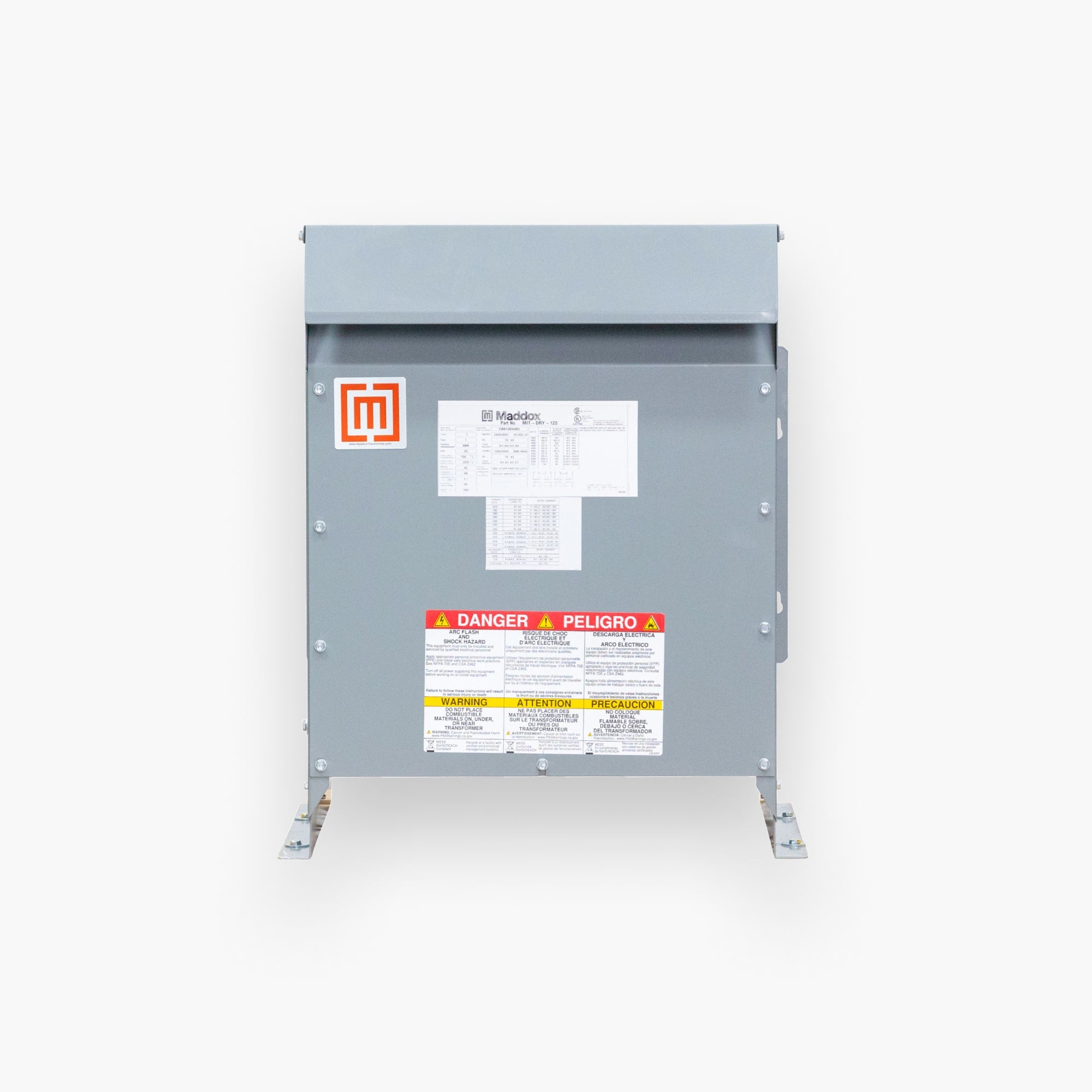
I think I found and appropriate isolating transformer. About the same price as the inverter! Oh well.
15 kVA 240 Volt to 120/240 Volt Single phase Isolation Transformer SC15C-K/Z3
Or a cheaper one with aluminum conductors:
15 kVA 240/480 Volt to 120/240 Volt Single phase Isolation Transformer SA15L-K/Z3
15 kVA 240 Volt to 120/240 Volt Single phase Isolation Transformer SC15C-K/Z3
Or a cheaper one with aluminum conductors:
15 kVA 240/480 Volt to 120/240 Volt Single phase Isolation Transformer SA15L-K/Z3
Hedges
I See Electromagnetic Fields!
- Joined
- Mar 28, 2020
- Messages
- 20,535
I think I found and appropriate isolating transformer. About the same price as the inverter! Oh well.
15 kVA 240 Volt to 120/240 Volt Single phase Isolation Transformer SC15C-K/Z3
Or a cheaper one with aluminum conductors:
15 kVA 240/480 Volt to 120/240 Volt Single phase Isolation Transformer SA15L-K/Z3
Here was a cheaper source (aluminum conductors).

1-Phase 240x480 - 120/240
This transformer converts either 240V 1-Phase or 480V 1-Phase to 120/240V. This unit is great for lighting, CNC machines, and other business machines.
Sometimes bargains found on eBay.
Hedges
I See Electromagnetic Fields!
- Joined
- Mar 28, 2020
- Messages
- 20,535
Thanks for that. When originally shopping for inverters, I also considered the MPP LV5048, which seems like it was two 2.5KW inverters mounted side by side in one case (no transformer?). Would something like that work in my setup, or would it have the same issue? Is the fact that the generator, load, and inverter input are all connected in the same junction box always cause issues?
I'm sorry for the very basic questions.
Yes, I think two separate 120V inverters creating 120/240V split-phase would avoid the problem.
When connected to grid, each sees grid voltage (may be 115V for one, 125V for other), and if they are interactive they add current to their phase.
But with no magnetics coupling them, there isn't that passive device mindlessly trying to balance the grid (or generator and workshop.)
RCinFLA
Solar Wizard
- Joined
- Jun 21, 2020
- Messages
- 3,561
Not entirely. Calibration tolerances in inverters' battery charging float/absorb voltage will cause a constant low level push as one inverter thinks it needs to raise float/absorb voltage and other thinks it needs to lower float/absorb voltage. This constant low level transfer usually flies in below the radar of inverters' zero export setting management.Yes, I think two separate 120V inverters creating 120/240V split-phase would avoid the problem.
Usually more significant, step variations in AC input phase voltages, caused by loads being turned off and on, by your house or your neighbors sharing same grid pole transformer, causes some pushing and pulling on AC phases even with zero export setting on inverters. It takes a finite amount of time for inverter feedback control to react.
The main difference with two series connected inverters is, instead of going through a single auto-transformer, it passes through inverters via battery node.
My two series connected inverters typically bounce around 1 amp of 'trading spit' between L1 & L2 phases as grid phase loading changes. It is also visible in a typical +/-1 to +/-3 amps bouncing around of 48v battery current. It usually bounces around more roughly around meal times when high current 120vac kitchen appliances or bathroom hair driers are likely being turned off and on and is not correlated to just my house. The settings for maximum bulk battery charging current effects the peak swapping current on my inverters. Part of the reason for my more visible bouncing is the old Trace inverters have coarser step adjustments on AC voltage regulation.
Last edited:
I'm communicating with Franklin at Sigineer and he is also flummoxed. Our back and forth reveled one aspect I still don't get. I understand that since the input to the inverter, all the loads, and the generator L1 and L2 output are all in the same transfer box, the inverter can "see" and try to balance the load draw regardless of its origin (house, shop, or barn).
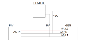
What I don't understand is when a 1100W (10 amps at 110V) heater is plugged into the L1 in the shop and the generator (because of the inverter transformers balancing) put out 5 amps on L1 and L2, how does the 10 amps correctly get delivered to L1 in the shop? The inverter input power shares the junction box with the in/out of the shop, but the inverter output only goes to the breaker box that feeds the house. Since the generator is putting out 5 amps on L1 and L2 (verified with a clamp meter around the hot wires) and the generator leads connect directly to the shop leads via the junction box, why don't the shop leads also reflect 5 amps on L1 and L2 instead of 10 amps and 0?
What I don't understand is when a 1100W (10 amps at 110V) heater is plugged into the L1 in the shop and the generator (because of the inverter transformers balancing) put out 5 amps on L1 and L2, how does the 10 amps correctly get delivered to L1 in the shop? The inverter input power shares the junction box with the in/out of the shop, but the inverter output only goes to the breaker box that feeds the house. Since the generator is putting out 5 amps on L1 and L2 (verified with a clamp meter around the hot wires) and the generator leads connect directly to the shop leads via the junction box, why don't the shop leads also reflect 5 amps on L1 and L2 instead of 10 amps and 0?
Hedges
I See Electromagnetic Fields!
- Joined
- Mar 28, 2020
- Messages
- 20,535
Without looking at a schematic ...
If inverter delivers 220V 5A, 110V 10A load is connected, auto-transformer is connected,
5A comes from L1 of inverter and goes to heater.
5A comes from L2 of inverter, goes through winding #2 of transformer to neutral, goes to other side of heater.
That explains 5A in heater.
If 5A goes though winding #2 of transformer,
then 5A is forced to go through winding #1 of transformer.
That 5A is added to the 5A from inverter, for a total of 10A through heater.
It's the magic of transformers. Power is coupled magnetically from one winding to another.
RCinFLA
Solar Wizard
- Joined
- Jun 21, 2020
- Messages
- 3,561
You have a 240vac to 120vac transformer involved. It is the inverter's transformer. Again, 240vac x 5 amp = 1200 watts, 120 vac x 10 amps = 1200 watts.I'm communicating with Franklin at Sigineer and he is also flummoxed. Our back and forth reveled one aspect I still don't get. I understand that since the input to the inverter, all the loads, and the generator L1 and L2 output are all in the same transfer box, the inverter can "see" and try to balance the load draw regardless of its origin (house, shop, or barn).
What I don't understand is when a 1100W (10 amps at 110V) heater is plugged into the L1 in the shop and the generator (because of the inverter transformers balancing) put out 5 amps on L1 and L2, how does the 10 amps correctly get delivered to L1 in the shop? The inverter input power shares the junction box with the in/out of the shop, but the inverter output only goes to the breaker box that feeds the house. Since the generator is putting out 5 amps on L1 and L2 (verified with a clamp meter around the hot wires) and the generator leads connect directly to the shop leads via the junction box, why don't the shop leads also reflect 5 amps on L1 and L2 instead of 10 amps and 0?
sunshine_eggo
Happy Breffast!
I'm communicating with Franklin at Sigineer and he is also flummoxed. Our back and forth reveled one aspect I still don't get. I understand that since the input to the inverter, all the loads, and the generator L1 and L2 output are all in the same transfer box, the inverter can "see" and try to balance the load draw regardless of its origin (house, shop, or barn).
What I don't understand is when a 1100W (10 amps at 110V) heater is plugged into the L1 in the shop and the generator (because of the inverter transformers balancing) put out 5 amps on L1 and L2, how does the 10 amps correctly get delivered to L1 in the shop? The inverter input power shares the junction box with the in/out of the shop, but the inverter output only goes to the breaker box that feeds the house. Since the generator is putting out 5 amps on L1 and L2 (verified with a clamp meter around the hot wires) and the generator leads connect directly to the shop leads via the junction box, why don't the shop leads also reflect 5 amps on L1 and L2 instead of 10 amps and 0?
I'm totally with you. The problem is @Hedges and @RCinFLA know way more than most mortals about this stuff. I've just resigned to the fact that I can't understand what they're telling us.
In my mind, this is what you're describing, and I don't see how:

Hedges
I See Electromagnetic Fields!
- Joined
- Mar 28, 2020
- Messages
- 20,535
I'm totally with you. The problem is @Hedges and @RCinFLA know way more than most mortals about this stuff. I've just resigned to the fact that I can't understand what they're telling us.
In my mind, this is what you're describing, and I don't see how:
View attachment 80656
Might have to do with my 60 years of amateur, professional, and academic experience.
You're entitled to not spot it without so much as a drawing in front of you. But seeing it, might make sense.
Now sketch in the auto-transformer.
(might be built in to inverter, or on AC Out of inverter)
sunshine_eggo
Happy Breffast!
Without looking at a schematic ...
If inverter delivers 220V 5A, 110V 10A load is connected, auto-transformer is connected,
5A comes from L1 of inverter and goes to heater.
5A comes from L2 of inverter, goes through winding #2 of transformer to neutral, goes to other side of heater.
That explains 5A in heater.
But he's measuring 10A in heater. How does L1 go from 5 to 10A?
Might have to do with my 60 years of amateur, professional, and academic experience.
You're entitled to not spot it without so much as a drawing in front of you. But seeing it, might make sense.
Now sketch in the auto-transformer.
(might be built in to inverter, or on AC Out of inverter)
I would if I could.
Hedges
I See Electromagnetic Fields!
- Joined
- Mar 28, 2020
- Messages
- 20,535
5A + 5A = 10A
Inverter drives 5A into L1, which flows through heater to Neutral, into center tap of transformer, and wants to go through lower winding of transformer to reach L2.
The only way 5A can flow through lower winding of transformer is if it (magnetically) shoves 5A in opposite direction through upper winding of transformer.
upper winding shoves 5A into L1, through heater, into neutral, back to center tap (completing a loop, back to upper winding.)
The 5 amps from inverter is allowed through lower winding, to L2, back to inverter (completing a loop.)
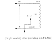
If you take a picture of an auto transformer (3 leads, 2 coils, sharing one core) and copy that onto this drawing, you can.
This one shows common, 115V, 230V.
Think of it instead as -115V, Neutral, +115V
(We usually don't call it - and + for AC, but I typed that as something you might follow more easily than "180 degrees out of phase" which is about the same thing for AC.)

Bud Martin
Solar Wizard
- Joined
- Aug 27, 2020
- Messages
- 4,843
Looking at the spec of the inveter, the AC input terminals of the inverter only has L1, L2 input, no Neutral input, inverter only accept 240V input.I'm totally with you. The problem is @Hedges and @RCinFLA know way more than most mortals about this stuff. I've just resigned to the fact that I can't understand what they're telling us.
In my mind, this is what you're describing, and I don't see how:
View attachment 80656
Just to follow up, I did end up installing two M3048NC and so far, so good. Loads in the house (which the inverters power) pull power from only their respective inverter. When the generator is running, the loads from the barn and shop are not affected by the inverters, and no unplanned balancing is going on. No transformers!
No transformers meant the inverters were much lighter and easier to install. Fans are much quieter. I also like that I can set the charge current separately on each inverter. So I can have the inverter on L1 supply 10A and the inverter on L2 supply 30A to my battery.
Thanks again to everyone here for helping me sort this out.
Similar threads
- Replies
- 19
- Views
- 737
- Replies
- 14
- Views
- 549
- Replies
- 8
- Views
- 328
- Replies
- 10
- Views
- 607


