diy solar

diy solar

An attempt to build a better SCC... next step.

rin67630

Solar Enthusiast
Joined
Apr 29, 2020
Messages
1,067
Location
Nort-Rhine-Westphlia Germany
After my first design to operate general buck-converters in a MPPT-mode by software upon controlling their CV setpoint in the feedback circuit, using low-power (<2A) buck converters, I would like to step up to an additional variants providing more power.
I have acknowledged, that I should first understand a bit more the way the different modules react.
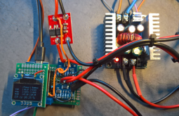
So I purchased five different buck-converters in the power range between 5 A and 20A and have first designed an intermediary power monitor.
  • XL4016 8A asynchronous buck converter with added CC/CV feedback circuit
  • BQ24650 synchronous buck solar controller with in-chip CV/pseudo MPPT feedback
  • XL4016 8A asynchronous buck converter with added CC/CV/pseudo MPPT feedback circuit
  • LM5116 synchronous buck converter with added CC/CV feedback circuit
  • CN3767 asynchronous buck solar controller with fixed in-chip pseudo MPPT feedback
1606129470423.png
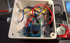
The power monitor is staging two INA226 off-rail current/voltage sensors, one for the panel side, the other one for the battery side which will record and track the input and the output power and compute the efficiency of the respective modules.
1606130105051.png
It will take me a certain time to evaluate all the modules and to select the most versatile and efficient one.
I will compare several chip technologies.
What I can already say today is that the red board staging a CN3767 solar controller chip dedicated to charge lead-acid batteries with inbuilt -non adjustable- thresholds, was a complete failure:
it charged the battery to 13,55V and stopped there, I had absolutely no way to go even close to absorption, not even to a decent standby charge level.
So I will put it immediately aside.
I will probably use the coming week to evaluate the other modules.
Stay tuned.
Regards
 
Last edited:
Finally it ran easier than I thought at first sight:
Here is my first test:
1606169577834.png
So you can see:
Panel 17,43V, 1,54A, 26,85W
Battery 13,70V, 1,91A 26,11W
Efficiency 97,25% at 25% panel power.

At very low load, the picture was a different one:
1606169890756.png

at 0,57 W to Battery, the efficiency is only 55% (that is partly due to the own power consumption of my test device)

I can test every MPPT, SCC that switch on the high side.
PWM SCCs switching on the low side cannot be tested on efficiency, since I get no measure of the panel voltage (which refers to a negative minus pole )
 
Meanwhile I have evaluated the efficiency of my solution, measuring the input and output power on a 400W buck converter.
I had some interesting findings:
If you leave the buck-converter alone, i.e. without injection into the feedback of potentiometer, you get about 95% conversion efficiency.
The feedback voltage is 1,22V irrespective of which output voltage is set.
Let us use 13.8V as an example.

One could imagine, that upon feeding the same voltage into the potentiometer over e.g. a 18K resistor, no change would happen.
Astonishing enough, that is not the case.

In order to be voltage-neutral, you need to feed 2,1V. Irrespective of whether feeding raw PWM or smoothing the signal with an in between capacitor, you need to feed more!
But then, my most alarming finding was: the overall efficiency of the buck converter drops below 88%.

I can't explain why, but the conversion is far less efficient when something interferes with the feedback circuit.
Currently my best deal with this approach is to refrain completely using PWM and use a tri-state control of the feedback potentiometer: wire a 18k resistor (without a diode) between my ESP8266 3,3V digital IO and the potentiometer, been set to 14,2V, the recommended cycling battery voltage.

Under normal condition the 3,3V digital IO is set to be an high ohm input and the buck converter regulates to feed everything it can to the battery with 95% efficiency.
From time to time, when the weather is fine with the solar panel being able deliver full power and the battery needs an equalization, set the digital IO to output, 0V for a couple of hours, that changes the set-point to 15.5V.
If for any reason, I need to disconnect the charging I can set the digital IO to output, 3,3V, that changes the set-point to 9,5V, which is pretty equivalent to stopping any charging process.

But anyhow trying to do an MPPT functionality by injecting PWM (raw or smoothed) into that buck converter is in fact killing more energy, than doing nothing.


Regards
Laszlo
 

Attachments

  • 1607520536512.png
    1607520536512.png
    553.1 KB · Views: 8
Finally, I could get a kind of voltage control that does not jeopardize efficiency:
3,2V PWM output to a massive RC low pass filter: 8,2K / 330microfarad, from there 47K to the potentiometer slider.
With the voltage potentiometer set to 14,4V (the recommended cycling voltage of my battery) I can get:
IO set to input, 14,4V 96% efficiency
IO set to output @ 55% PWM 14,4V 95% efficiency
IO set to output @ 0% PWM 15,3V 93% efficiency
IO set to output @ 72% PWM 13,8V 95% efficiency
IO set to output @ 100% PWM 12,9V 95% efficiency

That is enough to control my FLA battery charge as I want to run it.
Most of the time I will let it run with IO set to input.

Only when the battery is heavily discharged and need to limit a bit the current, or force an equalization to 15,2V, then I will switch the IO to output and modify the set point.

I will evaluate next summer if I can get an advantage with MPPT, but as far as I have seen with my 100W panel, the benefit will be limited.
 
Just to remember: here is one of the 4 internet dashboards provided:
Tablet view
1608415244451.png

Other example with instrumentation:
1608417718235.png

Hourly statistics:
1608417945878.png

LongTerm Trend
hourly voltage/ power and
daily Ah balance and voltage at 23:59:
1608418168516.png
 
Last edited:
Hardware selection finalized:
For low power 0-20W panels
the D-SUN buck converter:
1608647039445.png

That module is ideal for small loads, costs less than 1$, and with an additional heat sink it can provide 2A from 36V to a 12V lead-acid gel or LiFePo battery :
No-load consumption 0.2mA only.
It can be controlled over an injection into the potentiometer (own tests with potentiometer set to 13.8V)- - - - - - - - - PWM-Value:
Cvadjust 82K14.41V
190​
Cvadjust 82K10,29V
1020​
Cvadjust 82K13,81V
300​
Cvadjust 82K15.22V
0​
I can be switched off with an injection on pin2: enable Digital Low=OFF Digital High= ON.

Efficiency @ 10W 96,42%
1608645099205.jpeg

Efficiency @ 1W: 94% (try to beat that!) :
1608645581643.png
The efficiency @ 1W is important to be able to harvest some power with cloudy conditions, when the panel just will not deliver more...
(the most efficient PWM controllers will deliver 45%, MPPT controllers will deliver nothing: they need more power for themselves)

Next post will be for the mid-range power with a 100W 36cells panel.
 
Last edited:
Last edited:
Yeah, December is a problem. In oz we have to reduce the charge rate because there is so much sun it is too hot!
 
Yeah, December is a problem. In oz we have to reduce the charge rate because there is so much sun it is too hot!
:ROFLMAO:
Where are you in Oz?
It is also my problem here: in summer my 150Ah battery is full charged at 11:00 and I must throw the rest away and in winter, I can barely get 5W continuously.
At least you can operate a small DC-fridge to keep the beer cold.
 
Now testing the mid-range power with a 100W 36cells panel.
For that usage the best choice is this buck converter:
1608728259654.png
It has 17mA no-load current, has
1608728428590.png
a 66% efficiency at ~1W (roughly: in=out current) and


1608728559308.png
a 96% efficiency at 10W.

I still have to test it at 100W, I should have 18V a 7A power supply, or wait to get the half from my solar panel and feed the rest from AC, but the efficiency from 3w-25W was pretty constant, i don't expect much changes.

This is the best solution to power e.g a Raspberry Pi 3A from a 100W panel.

Next step will be to test the 250W solution.
 
1608750594399.png
The "medium power" IP67 box with 8A buck converter suitable for a 100W single panel is wired.
No-load power inclusive WiFi communication 25mA
Efficiency @ 1W 66%
Efficiency >= 10W 95%

The "medium power plus" IP67 box with 15A buck converter suitable for a 250W single panel will be very similar, only using another buck converter.
No-load power inclusive WiFi communication 40mA
Efficiency @ 1W 40% (less relevant)
Efficiency >= 10W 96%
 
Last edited:
How about adding support for a fan and temperature control?
The schematic variants in Github include output bucket controllers that can be controlled in voltage + enable. No problem to wire a fan to one of them.
I can consider including a rule based on the available outside temperature and the power to run a fan. So you can build it that way.
I could also consider adding the code for a LM75A I2C internal temperature sensor; it must be I2C: I have else no IO available.

For my own purpose, it will probably not be necessary. In summer I have excess energy anyway I can afford to throttle power and in winter when I have a rare sun ray it is cold enough and, due to the low sun, the panel will never deliver > 60%.
 
That'd be https://github.com/rin67630/Soft-Power ?? I realise excessive heat is not an issue you are concerned about but it's good to see you value adaptable design.
Yes, it it Soft-Power, next week, once my hardware tests are finalized, I will be going to update it heavily.

Regarding the hardware, on can also imagine placing the converter/heat-sink outside. The 15A converter has discrete MOS-FET Transistors that would be relatively easy to place on a large backside heat sink.

By the way: one of the 1000 ideas cycling in my head is a shunt regulation, running ventilators/Peltier elements to dissipate excessive energy...
 
Last edited:
The micropower IP 65 box is wired:

it provides:
Battery* loading up to 1.5 Amp from 12v or 24V grade panels.
Outputs: 5V 1A and 5-12V 1A switchable and voltage adjustable by software.
No load current including WiFi and MPPT ~7mA!
Efficiency at 1W 93%
Battery types: 3x LiPo 11V, 4x LoFePo 12V, 6xLeadAcid 13.8V
 

Attachments

  • 1609078995851.png
    1609078995851.png
    469.1 KB · Views: 151
Hardware selection finalized:
For low power 0-20W panels
the D-SUN buck converter:
View attachment 30996

That module is ideal for small loads, costs less than 1$, and with an additional heat sink it can provide 2A from 36V to a 12V lead-acid gel or LiFePo battery :
No-load consumption 0.2mA only.
It can be controlled over an injection into the potentiometer (own tests with potentiometer set to 13.8V)- - - - - - - - - PWM-Value:
Cvadjust 82K14.41V
190​
Cvadjust 82K10,29V
1020​
Cvadjust 82K13,81V
300​
Cvadjust 82K15.22V
0​
I can be switched off with an injection on pin2: enable Digital Low=OFF Digital High= ON.

Efficiency @ 10W 96,42%
View attachment 30992

Efficiency @ 1W: 94% (try to beat that!) :
View attachment 30994
The efficiency @ 1W is important to be able to harvest some power with cloudy conditions, when the panel just will not deliver more...
(the most efficient PWM controllers will deliver 45%, MPPT controllers will deliver nothing: they need more power for themselves)

Next post will be for the mid-range power with a 100W 36cells panel.
Hello!

I love your project and hope to benefit from your sharing as well!

I am searching for the same thing, finding the most efficient SCC module for a 20w solar panel. I also have the dsun controller but in my efficiency tests it performed really badly. It just down regulated the voltage and pushed the same current as the panel produces into the battery. The power from the voltage difference from panel and battery was completely lost. I wonder what modifications you did and if you would kindly teach me how to do it!?
So far the most efficient module I found out of the box has been the mppSET sd30crma. 92% - 96% you may have a look at this one for your up to 20w solution! It's also inexpensive, less than 3usd. For my 20w I had to put two of these mppSET controllers in parallel since they have a factory current limit of 1a. If one is able to do smd soldering one can change the current limit through changing a resistor. I can't so I had to get another one and put it into parallel in order to make use the maximum available power from the panel. With one controller only 14.7w went into the battery. With two controllers up to 19.7w of a 20w panel (but it can actually produce about 21w).

If the dsun controller would be as efficient as the sd30crma, as well cut at a set voltage like the sd30crma, I would prefer to use that one since smaller and I would not need to use two controllers/less power consumption. Further I could fit it better in my mini powerbox I am building. I use a 6ah and 10ah 13.2v lifepo4.

Further I am envious of your efficiency tester module, where did you get it from?
 
The micropower IP 65 box is wired:

it provides:
Battery* loading up to 1.5 Amp from 12v or 24V grade panels.
Outputs: 5V 1A and 5-12V 1A switchable and voltage adjustable by software.
No load current including WiFi and MPPT ~7mA!
Efficiency at 1W 93%
Battery types: 3x LiPo 11V, 4x LoFePo 12V, 6xLeadAcid 13.8V
Fantastic! ?? Exactly what I am looking for/trying to build as well!
I have a 22v 20w panel, 4s lifepo4 (6ah light version and 10ah a bit heavier version).
I just finished this powerbox/Bank yesterday.
IMG_20201227_220644.jpgIMG_20201227_220818.jpg
But I am stuck with the 10ah bigger version since I run out of space in the box. A smaller SCC would solve my problems! As well a better efficiency monitor with displays input and output like yours would be a dream!
 
Back
Top