diy solar

diy solar

An interesting drawing from Victron regarding Battery Balancing on a budget using 12V Batteries in Series/Parallel and cable sizing.

TerryTtibbs

New Member
Joined
Mar 15, 2022
Messages
56
This paragraph is in the VICTRON Documentation

In case of series-parallel connection, the midpoint
interconnecting cables must be sized to at least carry the current
that arises when one battery becomes open-circuited.
- In case of 2 parallel strings: cross section 50% of the series
interconnecting cables.
- In case of 3 parallel strings: cross section 33% of the series
interconnecting cables, etc.


There can't be a midpoint connection if there is only 1 string so the cable must be sized to at least carry the current is not applicable as their are no batteries in parallel.
The next part about 50% and 33% of the cross section of the Series connecting cables I am struggling to comprehend as the output Load of the bank could be drawn through any combination of the matrix of batteries with unmatching capacities in paralel if a battery has a complete open circuit and therfore a cable 33% of the load carrying capacity of the series connecting cables would possibly glow red before a fuse at the positive on each string could blow.
Or am I missing something?

To keep this post simple lets use some figures, so we are all on the same page when answering.

Batteries 12V 100Ah
Strings 4 x 12V 100Ah = 48V 100Ah per string
Combined parallel String = 3 x 48v 100Ah = 48V 300Ah Bank
Let's use the Wiring Diagram from the Victron Documentation
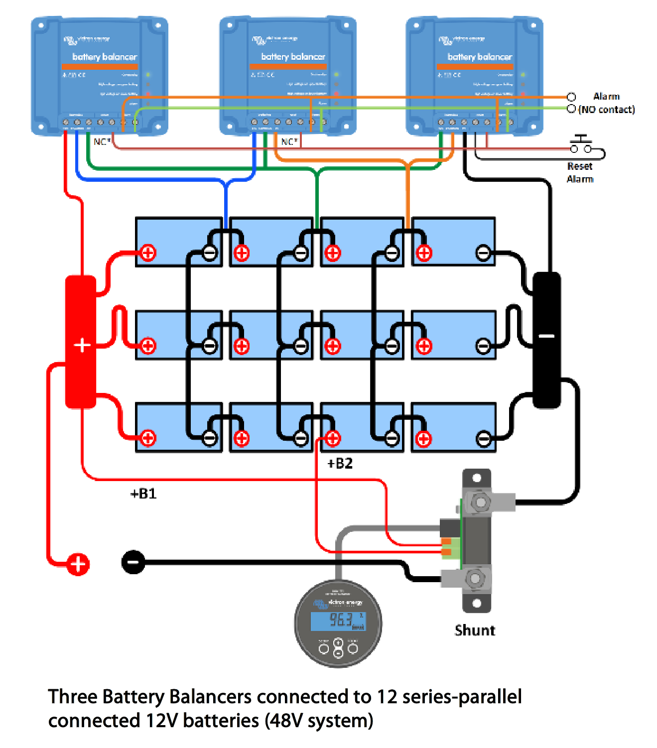
1648650237694.png

@smoothJoey https://diysolarforum.com/threads/lynx-shunt-wiring.37601/#post-475217
 
Last edited:
The issue comes with the battery balancer. Often there will be no parallel connections in the middle of the series battery strings. The parallel is handled by the bus. However with a balancer the mid-point parallels are needed or the balancer would only balance one series string.

So now that the system needs mid point parallel connections for the balancer, these wires need to have enough ampacity such that if a single BMS shuts down one battery and the current starts moving sideways. Otherwise the user might think the balancing is only a few amps and the interconnects for the balancing can be small. If the balancer is say 4 amps the user might think #16 wire is plenty. And it might be plenty until one battery shuts down and that #16 becomes a fuse.
I understand this, would it not be easier to just use a 10A fuse on each midpoint connection rather using larger cable and allowing 2 strings to become unbalanced in capacity?as the balancers in question are only 1amp charging.
 
I understand this, would it not be easier to just use a 10A fuse on each midpoint connection rather using larger cable and allowing 2 strings to become unbalanced in capacity? as the balancers in question are only 1amp charging.
 
I understand this, would it not be easier to just use a 10A fuse on each midpoint connection rather using larger cable and allowing 2 strings to become unbalanced in capacity?as the balancers in question are only 1amp charging.
That is 6 fuses and fuse holders vs the proper wire. May need more monitoring and not sure how that affects the balance alarm. Your call.
 
That is 6 fuses and fuse holders vs the proper wire. May need more monitoring and not sure how that affects the balance alarm. Your call.
There is more to it than this. This bank would still need fusing at the series and parallel points, anyway as it is now no longer series strings if it has full load carrying capacity interconnects; hence why I was looking at the design. The BMS only balances using 1amp per string divided by the 3 parallel strings. Batteries should always be fully charged to within 0.1V as the documentation states before grouping into parallel.

I was looking at it like this -

If the strings were left alone as 3 only tied at negative and positive bus bar, using 0.75mm interconnects in parallel to control the charge balance of the parallel strings (as the SOC should have already been equal through indivdual charging befoe comissioning). Using a small fuse on each midpoint interconnect, if a battery failed this would then pop the fuse and take the whole string down preventing a capacity inbalance in the other strings. Yes this would also not balance the other strings but this would only be short term until the faulty battery was replaced.

If the strings are connected in parallel using the same size mm2 cable as the series interconnects then all strings would contintue to function but with a massive capacity inbalance between the faulty string and the other strings. You would then effectivley have a string with less capacity than the others at the end of the series string, which would definately cause a problem and unless you have midpoint monitoring there would be no indication of a fault.

I am looking for people take on this.
 
Makes me think about using a resistor between the sets. Enough resistance to prevent fault burnout and low enough to enable the balancing to continue even if a bit slower. I assume the alarm would sound if there was a battery fault causing imbalance that could not be corrected.
 
There is more to it than this. This bank would still need fusing at the series and parallel points, anyway as it is now no longer series strings if it has full load carrying capacity interconnects; hence why I was looking at the design. The BMS only balances using 1amp per string divided by the 3 parallel strings. Batteries should always be fully charged to within 0.1V as the documentation states before grouping into parallel.

I was looking at it like this -

If the strings were left alone as 3 only tied at negative and positive bus bar, using 0.75mm interconnects in parallel to control the charge balance of the parallel strings (as the SOC should have already been equal through indivdual charging befoe comissioning). Using a small fuse on each midpoint interconnect, if a battery failed this would then pop the fuse and take the whole string down preventing a capacity inbalance in the other strings. Yes this would also not balance the other strings but this would only be short term until the faulty battery was replaced.

If the strings are connected in parallel using the same size mm2 cable as the series interconnects then all strings would contintue to function but with a massive capacity inbalance between the faulty string and the other strings. You would then effectivley have a string with less capacity than the others at the end of the series string, which would definately cause a problem and unless you have midpoint monitoring there would be no indication of a fault.

I am looking for people take on this.
Makes sense to me.
Better to be down one string.
Than to have the entire bank suffer.
Or worse.
 
Makes sense to me.
Better to be down one string.
Than to have the entire bank suffer.
Or worse.
Appologies for the anal aproach, but from my engineering and saftey point of view my biggest concern in any large capacity DC storage system is the protection of the batteries to prevent a fault condition that could effect many batteries. I can live with an invertor blowing or an MPPT and causing a bit of smoke, but losing control of a DC storage system is far more of a safety concern.

Are there
Makes me think about using a resistor between the sets. Enough resistance to prevent fault burnout and low enough to enable the balancing to continue even if a bit slower. I assume the alarm would sound if there was a battery fault causing imbalance that could not be corrected.
Makes me think about using a resistor between the sets. Enough resistance to prevent fault burnout and low enough to enable the balancing to continue even if a bit slower. I assume the alarm would sound if there was a battery fault causing imbalance that could not be corrected
any other electronic engineers on this forum that can validate my views?

regards

Makes me think about using a resistor between the sets. Enough resistance to prevent fault burnout and low enough to enable the balancing to continue even if a bit slower. I assume the alarm would sound if there was a battery fault causing imbalance that could not be corrected.
The alarm will sound when the comparison of voltages between parallel banks is @50-100mv out.
 
Last edited:
Makes me think about using a resistor between the sets. Enough resistance to prevent fault burnout and low enough to enable the balancing to continue even if a bit slower. I assume the alarm would sound if there was a battery fault causing imbalance that could not be corrected.
The only reason I ask these questions is that I have spent 3 weeks reading the Victron documentation and although I accept there will be minor errors in the documentation, this particular wiring diagram had me thinking for over a week on why you would connect series strings in this particular way.
Your idea about using a resistor would mean using a huge resitor (watts capacity) if it has to pass up to a 100amps from the string in peak situatuations with say a 3KW invertor on peak.
Anyway it was just my curiosity that made me ask for other peoples opinions and thank your for the contribution.
 
@time2roll @timselectric

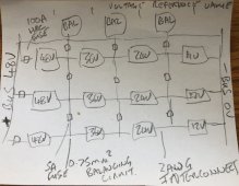
Now for the worst wiring diagram ever shown on a public forum! I don't have time to design on software so just jotted it down a some scrap paper. Please accept the disgusting hand writing.

This is what I was thinking.IMG_0444.JPEG
Interconnecting cables 0.75mm2, 9x5A fuse on each parallel interconnect
2AWG on the main series interconnects and to bus bar
Strings to bus bar protected by 3 x 100amp fuse HRC or some appropriate fuse that can contain itself when you drop your spanner
Voltages on batteries just for reference
The small yellow thing on the 36V reference area is a piece of garlic bread and not part of the circuit.
 
Last edited:
Only need to pass 1 or 2 amps to cover balancing. Enough resistance such that if a battery did shut down the voltage differential would not cause the resistor any harm.

If the differential during a fault was 14 volts and the resistor was 14 ohms then only 1 amp and 14 watts would pass, not 100 amps. The low 14 ohm resistor might still allow the balancer to work. I don't know if 14 is the correct number.
Yeh,
 
The whole battery bank with 3 strings is carnage anyway and should be done with 6V or 2V cells but I aquired the 12V deep cycles for 1/8th of the price and don't care if they are trashed after 3-5 years as Lithium and Sodium will be cheap as chips by then.
 
If a battery might shut down I am thinking it is LFP with a BMS. Lead-acid should not shut down except for a drop due to a shorted cell.
Not even sure I would bother with the balancers. Periodic equalize should keep them straight. I would be more concerned about watering 72 cells.

Unless there is a significant change of materials I don't expect prices to drop much. I believe the world is entering a time of peak everything with all resources limited and priced accordingly.
To be honest your right, you could just use 0.75mm2 interconnect cables and 5 amp fuses without any balancers and providing the cells are all new and charged individually first then they should be ok. It's all down to each cell but in the real world I will find out.

Going back to the original drawing posted, I won't be using 2awg interconnects for the midpoint as in the Victron documentation. I would rather pop a skinny 5A fuse and save my string getting boiled, do you agrea?
 
I would save the hassle and have no mid-string parallel connections at all. The bus is the only parallel. The mid-string parallel is just for the balancer that can be skipped.
 
For me, this is only a thinking process.
As I would never build a bank like this.
I like to keep things simple.
If I had to use these batteries, it would be wired as 3 separate batteries.
Then put in parallel.
If extra balancing was required, then 3 separate balancers.
 
For me, this is only a thinking process.
As I would never build a bank like this.
I like to keep things simple.
If I had to use these batteries, it would be wired as 3 separate batteries.
Then put in parallel.
If extra balancing was required, then 3 separate balancers.
Agree, and this is why I wanted peoples opinions on the Victron diagram showing using only 3 balancers across the whole bank.
another consideration is that if you use the 2AWG mid point interconnects as they suggest you would then idealy need to fuse each battery as they are now in parallel, which would effect resistance for the balancers.

Thanks again for the input.
 
It appears my post was deleted?

I posted this:


1 of these on each string. Done.

I use similar devices on my 4S2P Trojan bank.
 
Back
Top