diy solar

diy solar

An issue in balancing LifePO4 battery cells' top and bottom

flashmark

New Member
Joined
Nov 4, 2022
Messages
70
Hi.

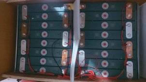
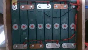
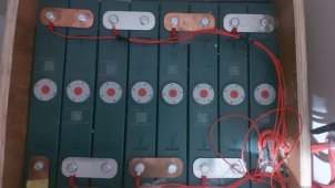
We are building a 3.2v 16 cells Lifepo4 pack, with JK BMS.
We did bottom balancing and top balancing of the pack.

But now some cells get over discharged and the cell volt difference is 0.5mv. (Also, observed that the cells gets over charged to 4v on the previous day).

In this case, 5 cells were at 2.7v and the remaining were at 3.24v.
1667611830417.png

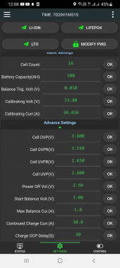
Here is the setting of JK BMS (screenshot took bit later)
1667612199234.png

How do we set the parameters correctly to balance the pack at “top” and “bottom” both?

Your advice is highly appreciated.

Thanks,
Flash
 

Attachments

  • 1667611884243.png
    1667611884243.png
    261.9 KB · Views: 7
How did you top balance the cells exactly?

I think your balancing starts too low, I’d adjust to 3.35v
 
You can't do both. You have to choose one or the other method. For 99% of us, that is top-balancing.

You may have inadvertently badly UNbalanced this bank trying to do both.

Your start-balance volts should be 3.45v or slightly higher, like 3.50 or even 3.55v if you choose. Top balancing is done while in the middle to top part of the charge knee, which means being *above* 3.4v for your start balance.

Start with 3.45v as the start-balance, and see how that goes.
 
Last edited:
Starting balancing above 3.4v is fine. The higher you raise the start of balance point the less 'runway' you have to balance cells before one of them goes to overvoltage limit.

If you do get an overvoltage cell before all cells achieve full charge you can lower your charging rate to make the charge to balance current ratio closer to one. Once they get balanced again you can raise your charging rate.

Balancing at lower voltage, in flat portion of LFP discharge curve, can cause misbalancing.

This is most likely to happen when you have rather low charging current and higher balancing current. Any cell current, whether charge or discharge, has some cell overpotential terminal voltage shift created, bump up for charging, slump for discharging. When balancing current dominates the cell overpotential, over that created by charging current which is applied to all cells, it can cause balance voltage sensing to read artificially high or low cell voltage triggering an incorrect balancing direction decision. This issue is at its worse when balancing occurs at no charge or discharge current conditions.

The cell overpotential voltage has an exponential decay for recovery time so even when balancer momentarily stops balancing when making cell voltage measurements the recovering overpotential can still be read as a higher or lower than actual OCV cell voltage. When charging current is much greater than balancing current the charge current will dominate the cell's overpotential so the extra overpotential due to balancing current is insignificant.
 
Last edited:
DO NOT USE THAT CHART.

Most are based on non-charge resting voltages, and are innacurate to boot. There is only one voltage listed that shows under charge. The chart thing is in another dedicated thread.

Here, the bms values discussed are based upon CHARGE values for one thing.

That chart would only serve to distract and confuse others when setting their bms.
 
Should I start at 3.35? Isn't it too high?

It is TOO LOW if you are doing a top-balance. 3.45v or higher is recommended.

Again, you can't do both top and bottom balance. AND, most BMS' are designed for top-balance, not bottom balance, which is an old technique EV'ers and some others used - but with a lot of prior knowledge of WHY they are doing so.
 
I'm with Supervstech - my *sense* is that an initial top-balance was not performed, and when the bms was added, you encountered a lot of runners.

Perhaps someone suggested bottom balancing, and your CV start-balance voltage was adjusted low to check it out, but that too proved unfruitful?

Nothing accusing here, but just trying to get on the same page. If it hasn't been done, we can focus on that first and help out.
 
It is TOO LOW if you are doing a top-balance. 3.45v or higher is recommended.

Again, you can't do both top and bottom balance. AND, most BMS' are designed for top-balance, not bottom balance, which is an old technique EV'ers and some others used - but with a lot of prior knowledge of WHY they are doing so.
What should we need to set in the hybrid inverter as a cut-off V? Assuming If we set the start balancing voltage as 3.45?
 
Probably the best thing to do now is to go here and do the initial top-balance. That is not done by bms alone, it requires a programmable / variable benchtop power supply, or even the so-called "single cell nominal 3.2v charger". This is the sanity-balance. :)


Afterwards, these values will make much more sense in your bms setup.
Since the battery pack already is already connected, can I do this with an inverter?
 
If you can limit your inverter's output voltage to 3.6v regulated you can. But you'll be either charging them individually, or in parallel as one big cell first before using the bms. Details in the how-to.

If you don't want to disconnect the whole pack, then the individual charge to each cell first, looks to be the way you are wanting to go.

OR, you are going to do the cowboy-dance with a big automotive headlamp temporarily connected to each cell trying not to let them go above 3.6v. With a multimeter in hand. For 16 cells, you'll be dancing quickly. That's really old-school, but possible to get at least in the ballpark. Very easy to not dance fast-enough, and hurt a cell as it skyrockets. That's kind of what your bms is trying to do, but the current is swamping the bleeders, and it trips the bms protect anyway.
 
Last edited:
Yep, nothing to do with the grade however. Top-balance regardless of grade, is 3.45v or higher as the balance voltage start trigger.

HOWEVER, once that sanity-balance has been performed, either by initially top balancing manually with a variable power supply, or some other method to individually charge the cells to near equal SOC, a bms with bleeder resistors can "fine tune" it when it is applied afterwards.

After a sanity-balance has been achieved, if one wants to run conservatively, they can drop their CV in the bms to just *under* 3.4v, like 3.375v for regular cycling to ensure the battery will never reach, or even try to reach, a full charge. But a top-balance sanity check has to be done first.
In my experience, the voltage curve of grade B cells is more unpredictable. In my Lanni pack (which I presume does not use genuine grade A cells), the highest and lowest voltage cells in the 3.35V range are not the highest and lowest voltage cells in the 3.5V+ range. The cells in my new grade A pack do not do this.
 
In my experience, the voltage curve of grade B cells is more unpredictable. In my Lanni pack (which I presume does not use genuine grade A cells), the highest and lowest voltage cells in the 3.35V range are not the highest and lowest voltage cells in the 3.5V+ range. The cells in my new grade A pack do not do this.
There are no specific cells with this behaviour. Basically, it happening in randomly.
 
Randomly? That might point out a wiring / high-resistance issue like alligator clips instead of cleaned bus-bars. :)

How about setting the bms to 3.450v as the start-balance value, and if you have runners, use a lower charge current if doing a true sanity-balance beforehand can't be done?
 
Randomly? That might point out a wiring / high-resistance issue like alligator clips instead of cleaned bus-bars. :)

How about setting the bms to 3.450v as the start-balance value, and if you have runners, use a lower charge current if doing a true sanity-balance beforehand can't be done?
Randomly means it happens to cell 1.4.6 at one time and the next time it happens to cell 4,8,10 etc.
 
Randomly means it happens to cell 1.4.6 at one time and the next time it happens to cell 4,8,10 etc.
I agree, this is sounding like aluminum corrosion (which is invisible) on the bussbars, or other oddities in the connections.

Let’s start with some close up pictures of the build.
 
1.jpeg
I agree, this is sounding like aluminum corrosion (which is invisible) on the bussbars, or other oddities in the connections.

Let’s start with some close up pictures of the build.

These cells are not brand-new cells. Imported from China (Not sure about the grade).
 

Attachments

  • 2.jpeg
    2.jpeg
    83.7 KB · Views: 11
  • 3.jpeg
    3.jpeg
    68.5 KB · Views: 11
  • 4.jpeg
    4.jpeg
    112.4 KB · Views: 12
Last edited:
Back
Top