


You are using an out of date browser. It may not display this or other websites correctly.
You should upgrade or use an alternative browser.
You should upgrade or use an alternative browser.
ANL fuse vs Circuit Breaker
- Thread starter JimF
- Start date
John Frum
Tell me your problems
- Joined
- Nov 30, 2019
- Messages
- 15,233
The feeder and branch topology has this covered.@smoothJoey - Wires/charger/controller …. Any device can sort out or fail and draw excessive current. It depends on the device’s tolerance, but having a fuse that allows double overcurrent for up to 300 seconds seems excessive and a danger to me. The MPPT controller, AC charger and the two medical devices I need to provide backup power to (CPAP machine and O2 concentrator) will obviously have much smaller fuses than the main 100A fuse on the battery, however it appears all fuses, even “fast blow” have significant delays in an overload condition. Yes, I know I’m being overly cautious In the opinion of many people.
The battery circuit is the feeder circuit and should be fused as closed as possible to the battery positive terminal.
The feeder circuit gets the high AIC fuse because the dead short current is highest on the feeder circuit.
The branch circuits are all fused at the busbar according to the wire gauge for that circuit.
The branch circuit fuses are there to protect the smaller gauge wires and also to isolated faults to a single circuit if possible.
These fuses don't require as much breaking capacity as the dead short current is lower because they are further away from the battery.
The main fuse is there as a backup to the BMS and incase a branch circuit can't quench an arc.
Passive devices that do not have their own over-current protection need to be considered as part of the circuit and considered in the fusing decision.
Depending on the built in over-current protection of devices like MPPT controllers and ac chargers they don't necessarily need to be considered for the circuit fuse.
My policy is not to buy un-protected devices when protected options are available.
Hope that is clear.
Last edited:
Thanks much @smoothJoey. good advice and sounds like what I am planning. 100A main battery fuse and battery switch very close to battery, then two branch circuits, one high amp breaker for inverter only and the other 25 amp breaker feeding a Blue Sea ATO-fused distribution block. Both medical devices I am backing up have cigarette lighter auto plug, which are unreliable. I may cut the devices’ cords and insert/use Powerpole connectors that I have used for many years with very high reliability. I’ll keep the cigarette lighter ends in case I need to go mobile. I’m also putting in dual 15A solar input breakers (+ & -) , MPPT output breaker and a fourth breaker for the Victron IP67 17A charger.The feeder and branch topology has this covered.
The battery circuit is the feeder circuit and should be fused as closed as possible to the battery positive terminal.
The feeder circuit gets the high AIC fuse because the dead short current is highest on the feeder circuit.
The branch circuits are all fused at the busbar according to the wire gauge for that circuit.
The branch circuit fuses are there to protect the smaller gauge wires and to isolated faults to a single circuit if possible.
These fuses don't require as much breaking capacity as the dead short current is lower because they are further away from the battery.
Passive devices that do not have their own over-current protection need to be considered as part of the circuit and fused accordingly.
Depending on the built in over-current protection of devices like MPPT controllers and ac chargers they don't necessarily need to be considered for the circuit fuse.
Hope that is clear.
I appreciate the tips.
Last edited:
John Frum
Tell me your problems
- Joined
- Nov 30, 2019
- Messages
- 15,233
A dc fuse block is great solution for the low current stuff.Thanks much @smoothJoey. good advice and sounds like what I am planning. 100A main battery fuse and battery switch very close to battery, then two branch circuits, one high amp for inverter only and the other 25 amp feeding a Blue Sea ATO-fused distribution block. Both medical devices I am backing up have cigarette lighter auto plug, which are unreliabl. I may cut the cords and insert/use Powerpole connectors that I have used for many years with very high reliability While retaining the cigarette lighter ends in case I need to go mobile. I appreciate the tips.
Put a 100 amp fuse and 6 awg wire on the fuse block feeder circuit.
The fuse block branches can be up to 10 awg with a 30 amp fuse which means 24 service amps.
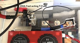
You will want a class FAST ACTING T fuse directly to battery but consider the rating of your inverter. If the inverter is 2,000/4000W (for example) or ~300A max + 25% surge , I'd recommend a 350A Class T fuse on the battery positive terminal and a 275A ANL between the Pos bus bar and the inverter. That way, if the ANL fuse arcs and welds itself together, the T Class will immediately blow. It is unlikely that the ANL will fail like that but if it does, you want to be protected because that would likely end in a fire.I assume best to attach the class T fuse directly to battery terminal, then to battery shutoff switch?
This may not be the best way to add the T-Fuse but it's the way that I did it. I put a plastic outlet box over the fuse for protection.
Attachments
Last edited:
I'm thinking that test must have used a "Slow Acting T Class Fuse". For best protecion from a lithium fire, one would want a "FAST Acting T Class Fuse".Blue Sea 285 series breakers are marginally better response time than either Class T or ANL fuses. They are rated for between 10 and about 35 seconds @ 200% current, though AIC rating is only 3000A @ 48v - no idea if that changes for 13.4v. So I might use both a fuse and a breaker on the positive side.
View attachment 100209
Bluedog225
Texas
- Joined
- Nov 18, 2019
- Messages
- 2,892
Interesting. If that box were dropped on it’s side, is the class t fuse part of the structure keeping the conductors apart?You will want a class FAST ACTING T fuse directly to battery but consider the rating of your inverter. If the inverter is 2,000/4000W (for example) or ~300A max + 25% surge , I'd recommend a 350A Class T fuse on the battery positive terminal and a 275A ANL between the Pos bus bar and the inverter. That way, if the ANL fuse arcs and welds itself together, the T Class will immediately blow. It is unlikely that the ANL will fail like that but if it does, you want to be protected because that would likely end in a fire.
This may not be the best way to add the T-Fuse but it's the way that I did it. I put a plastic outlet box over the fuse for protection.
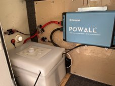
Good question.... The battery box is sunken 3"into the floor and secured.Interesting. If that box were dropped on it’s side, is the class t fuse part of the structure keeping the conductors apart?
Attachments
Saw these mentioned on the off grid garage channel: TAIXI Molded Case Circuit Breaker, 2 pole. Any thoughts as its apparently faster than class T and can get them for my needs which is 2p8s 280Ah batteries. Not sure about arc'ing etc as I'm new.
It's half way down this page.

It's half way down this page.