diy solar

diy solar

ANT BMS incorrect voltage reading on cell #1

erickh

New Member
Joined
Jan 13, 2020
Messages
11
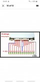
Hello all, I installed a new ANT BMS on a 16S LiFePO4 pack I made and I can't get cell #1 to read correctly no matter what I try. All other 15 cells read correctly. I have tried working with the ebay seller, icgogogo, as I feel like I got a bad BMS and they keep saying my wiring is incorrect, yet it matches their documentation. Here is a picture of how I currently have it wired. To those who have worked with this BMS, is this correct or am I missing something?

BMS-Setup.jpg
 
As a test on wiring i test the plug with a volt meter. You ave find short wire to insert in first hole which is usually black wire. Then the next wire should read one cell. Then the wires should step up by the voltage of a cell until you get to the end. The last value should be the pack voltage. The holes in the connectors are close together so I keep insulation on most of the first wir and bend it out of the way to avoid a short.
 
Thanks for the suggestion! I've done that to test the wiring harness itself for broken wires, etc. All my connectors are crimped and soldered and all work, but I'll go through again and check the voltages over once more, though I've done it a few times.
 
If I remember correctly, the way they work is the positive of the first cell is negative of the next cell and so on. That would tell me the suspect wire is the first negative if only the first cell is not reading. Does that make sense?
 
I'm not sure if what you're saying makes sense, but I do agree it should either be the first cell positive balance wire or negative balance wire, if a wire were faulty, which none are. Here is the wiring diagram provided by the seller, which my setup should match.


s-l1600.png

At this point I'm still going with faulty BMS unless someone can specifically point out what the problem with my wiring is. I have another BMS on the way which I will test upon arrival. If anyone else has any suggestions of how to test, I'm all ears!
 
Using your diagram, if the wiring is correct you should see cell voltage from black wire in right connector to the next red wire for cell #1. Then from that red wire to the next red the same cell voltage for cell #2. You already verified that from black wire to cell #2 was double the cell voltage (ie two cells).
I was just offering that diagnostic to help your dialogue with the vendor to convince them that the internal electronics are bad. I assume you also checked the red wires against the thick black wire going to negative terminal post?
 
@erickh .... have you seen some of the threads about this seller? Might want to do a search.

It sure sounds like a bad BMS if the voltages are all correct at the plug. Seems like the negative wire would be OK if the BMS is reporting the pack voltage correctly.
 
I appreciate the help. I'm looking for any tips or indicators I'm doing something wrong. If I am, I want to know, but they ensure me my wiring is wrong.

I just checked all voltages from the balance wires and here are the values (Note: My meter is not very accurate, these voltages are a lot closer than they appear, but of course I haven't balanced the cells yet as my BMS wasn't working).

1589221674438.png

So, this would indicate that my wiring is correct and the BMS is indeed faulty. @Bob B No I have not. By that, I'm guessing there have been other issues with the seller and BMS? Also the BMS is not reporting the pack voltage correct, because cell #1 reports about 0.9 volts, so it's a couple volts low. It is also "dropping" cell #1, which effectively turns the BMS off as it thinks cell #1 is faulty.
 
Also the BMS is not reporting the pack voltage correct, because cell #1 reports about 0.9 volts, so it's a couple volts low. It is also "dropping" cell #1, which effectively turns the BMS off as it thinks cell #1 is faulty.
It could be as simple as a bad pin on the cell #1 receptacle but in any case the only other way to verify is to plug in another Bms or a cheap CellLog or similar and send them a picture. Your chart should also be proof. I am not sure you want to buy another similar one but you could always do that and cancel the first transaction if they won't take the bad one back.
 
There was a thread about them .... but I couldn't find the main one. Some are calling them ICNONO ..... A lot of people have had bad experiences with them.
 
See here:

 
In this video, the guy has a problem with readings on cell #1 as well. About 5min into the video he discusses it. Also somewhere else in the video, as I recall.
 
Just my sixpence worth, I purchased from the same people for my 14s100p installation, the only issue I had was they sent the wrong drawing for my BMS but I must say it appears to be working well, I have no affiliation to them I must add, Just for information I've enclosed my ANT BMS wiring diagram just in case anyone here as the same problem I did.
.
 

Attachments

  • Screenshot_20200702-044950_eBay.jpg
    Screenshot_20200702-044950_eBay.jpg
    43.5 KB · Views: 29
In this video, the guy has a problem with readings on cell #1 as well. About 5min into the video he discusses it. Also somewhere else in the video, as I recall.
This is what I need for cell 2 on mine but I can't seem to find where one can calibrate on ANT BMS. Voltage on cell 2 is incorrect compared to figures from my voltmetre. Has anyone who experienced been able to resolve it?
 
I had the same issue as erickh where cell 1 was showing 0.3v instead of 3.2.. Problem was solved by connecting the blue side of the bms wire to the battery not the black side...

 
I had the same issue as erickh where cell 1 was showing 0.3v instead of 3.2.. Problem was solved by connecting the blue side of the bms wire to the battery not the black side...

That sound wrong, mine happen to be contact issues
 
Back
Top