diy solar

diy solar

anyone wanna help me convert my 12v diagram to 24?

Attachments

  • 1632598794511.png
    1632598794511.png
    41.9 KB · Views: 2
Yes, those will work fine. (You only need the fuses if you have three or more strings in parallel)
i think will prowse mentions that these epever scc's will play nice together but maybe it's worth it to flip 'em and just buy one that'll accommodate 1200 watts. is there one you'd recommend?
In general, more controllers are better if you have shading conditions.... but of course more controllers will complicate the wiring.
One of the EPEVERs will accommodate all the panels, but if they produce at peak rated power, it will not use all of the power.
Two or 3 of the EPEVERs will accommodate the panels can do without limiting the power.

If you do want to buy a single controller that can handle 1200W or more, I would go with the Victron 150/45. It is expensive, but rock solid.
 
BTW: Panels rarely produce at their rated power. There is a reasonable chance that your panels would never be limited by using a single one of the EPEVERs. This is particularly true with the panels sitting flat on the roof and not angled at the sun.
 
updated the diagram:

- should i just get the 30amp victron orion? future proof it incase the dc load increases?
- i guess the diodes should be 10 amps? same as the fuses were?
- can the fuse to the batteries be smaller now that they're running as 24v?
- the original vanlifeoutfitters diagram has the lynx distributor fuses as pictured (attached). should i just keep 'em the same?
- did i forget anything?

thanks for your patience. i haven't been to CA in years?
 

Attachments

  • lynxdistributorfuses.png
    lynxdistributorfuses.png
    407.8 KB · Views: 7
  • newdiagram2.png
    newdiagram2.png
    232.8 KB · Views: 9
updated the diagram:
The diagram looks good except....
1) The 2nd EPEVER needs to be hooked to the Lynx.
2) There is a fuse added to the line going to the inverter. I don't think that is needed. Just put a 200A fuse in the Lynx.
3) The 400A fuse on the battery is too big. That should be dropped down to a 225 or even a 210 if you can find it.
4) The wires to the Orion can be as small as 12AWG. (10AWG if the Orion manual wants a fuse larger than 20A)
5) Does the EPEVER have a case ground lug? If so, there are getting to be too many negative wires into the Lynx. ( It is not good to put too many lugs on top of each other. ) I would be tempted to buy a separate grounding bus bar and tie all of the following to it:

* Chassis Ground
* Inverter Case ground
* EPEVER Case grounds
* Lynx side of the Smart Shunt (Where the chassis ground connects now)


- should i just get the 30amp victron orion? future proof it incase the dc load increases?
I never heard what your DC loads are. If they are under 30A it is a judgement call on whether to future proof.
- i guess the diodes should be 10 amps? same as the fuses were?
The diodes can be 10A or higher. The 20A ones you linked to would work.

- can the fuse to the batteries be smaller now that they're running as 24v?
Yes. As commented earlier, the battery fuse can be as low as 210A.

- the original vanlifeoutfitters diagram has the lynx distributor fuses as pictured (attached). should i just keep 'em the same?
You will have 4 fuses in the Lynx:

1) Inverter - 200A
2) 24/12-30 Victron Orion - 20A (Check the Orion manual, they may recommend something larger, but a 20A should be close )
3) EPEVER 1 - 50A.
4) EPEVER 2 - 50A

- did i forget anything?
Probably... but I don't know what :)
 
ok, the vitron lynx actually has 5 more negative bus bar attachment points that weren't shown on the previous picture because plastic levers were obscuring them. should be able to get everything on there rather than buying another. made all the other changes. switched the fuse to the batteries to 175a on the recommendation of an electrician friend cuz he sais that's what 4/0 wire is rated for. found this battery disconnect switch:


do you know how many amps it would need to be rated for?
 

Attachments

  • newdiagram3.png
    newdiagram3.png
    248.3 KB · Views: 6
  • PXL_20210927_211342913.jpg
    PXL_20210927_211342913.jpg
    163.2 KB · Views: 6
Last edited:
switched the fuse to the batteries to 175a on the recommendation of an electrician friend cuz he sais that's what 4/0 wire is rated for.
Hmmm.... 175A is too low for the battery unless you will never drive the inverter and DC at full load.
If you get Marine rated wire, I believe it is rated for more.

1632794642531.png
1632794923103.png

the vitron lynx actually has 5 more negative bus bar attachment points that weren't shown on the previous picture because plastic levers.
Good. I thought it was kinda odd that they did not have more negative posts.

found this battery disconnect switch:

https://www.amazon.com/gp/product/B07MQ54KKH/ref=sw_img_1?smid=&psc=1
do you know how many amps it would need to be rated for?
The description says 275@12V..... but does not list 24V or 48V ratings.

The fact is, the switch will probably work but this brings up another thing to discuss: Inverter Pre-charge. Are you familiar with what that is?
 
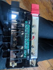
All inverters have Big capacitors accross the DC inputs.

1632796981025.png

These capacitors will look like a short circuit when you first hook DC to the inverter. The capacitors will quickly charge but in the first moments the current can be huge. The outward sign of this is that you get a big-ass spark when you touch the power line to it. The spark can be big enough to pit the threads on a post. There has been debate on the forum about how harmful this is to the capacitors and the BMS. I don't know about the capacitors or the bms, but I do know that the current can be high enough that the BMS can think it is a short circuit and shut down. (Even if it does not hurt anything, you may have to change your underwear the first time it happens! :))

The bigger the inverter, the bigger this issue is.... On a 1000W inverter I would probably not worry about it but when you get to 3000W, it is getting in the zone where it is something to worry about.

If you are going to hook up the inverter once and never unhook it, what you do is get a ~10 ohm resistor and put it between the battery and positive cable for a few seconds to pre-charge the capacitors, then you can directly hook up the cable without a spark.

1632796843296.png


If there is a switch in the circuit, the same thing happens every time you turn it on..... but you may not see the spark.

1632797939543.png

Even though you can't see it, the spark is almost certainly pitting the switch and the surge may be damaging other components.

One common approach is to put a resister and push button around the switch.
1632798388650.png

With this, you push the button for a few seconds before you turn on the switch.

I came up with a slightly different arrangement with this:
1632798732221.png
 
k. so just wrap a resistor between the switch and the distributor? like this?


Attachments

  • newdiagram4.png
    newdiagram4.png
    249.5 KB · Views: 8
uh, well, how big of a concern is this if i won't commonly be switching the battery switch to off?
 
uh, well, how big of a concern is this if i won't commonly be switching the battery switch to off?
Well.... it is hard to say for sure but *probably* not a big deal..... I personally decided not to take the chance and built the precharge switch that I provided the link to.
 
i'm trying to assess my 12v load so i buy the right dc to dc converter. i've got a fresair that says it consumes <10a/h at full power, a12v rv waterpump from flowmax that says 9.5 amps max, i'll prolly buy a dometic fridge that i think is 10.4 a/h rated input current plus whatever a few leds consume.
 
Hmmm..... The actual loads will probably be a little less than the name-plate load so you are probably at about 30A.... but it sounds like 30A is the absolute smallest converter you should get.
 
ok. i'm getting two of these circuit breakers to run from the panels into the sccs.


also, i'm having trouble finding fuses that'll fit in the lynx distributor? like i'm pretty sure this one will:


but i'm having trouble finding the 20a and 50a ones.
 

Attachments

  • newdiagram4 (1).png
    newdiagram4 (1).png
    281.8 KB · Views: 4
About the drawing.

* If you will be using the large 70A DC/DC converter you linked to, the fuse for it is going to need to be much larger.
Assuming a 90% efficiency, the fuse will need to be (70/2)/.9 = 39A The fuse should be 25% larger so it needs to be 1.25*39=48.6. Round that up to 50. Also, the wire to the converter needs to be 8AWG Marine grade wire. The wire coming out of the converter needs to be larger as well.

* The 175A battery fuse is too small. I originally came up with the 125A recommendation based on the 30A dc-dc converter. With the 70A converter, the size will need to be increased:

164A from the inverter
39A from the converter
203 total

1.25 * 203 = 253. (Since you probably will never run max on either the inverter or converter, let alone both), let's call it 250A fuse for the battery. 4/0 marine grade wire should be OK for that.

The lynx distributer takes Mega-Fuse style fuses. They tend to only be available in larger sizes but I have seen them as low as 40A
 
ok. made those change. thanks.

i'm not sure how i'll wire these batteries. it'd be straightforward if they didn't take these stupid anderson connectors:


Attachments

  • newdiagram5.png
    newdiagram5.png
    249.6 KB · Views: 4
Back
Top