It didn't work at ~3 volts. (BMS remained unpowered) I assume the internal electronics need higher voltage between the positive BC8 sense lead and negative.
Warning: I have to idea how safe this is for the BMS. Copying anything I'm doing here is obviously at your own risk. ")
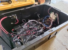
What did seem to "work" (at least partially) was to leave the white sense leads BC1 thru BC7 disconnected, tie the black sense lead to B- and supply 22 volts across BC8 and B-. (I'm testing with a JBD-SP10S009)
This produced some bizarre cell voltage numbers since the cell sense leads were all floating, but did at least allow the BMS to come online and be reachable via the bluetooth module.
View attachment 66943