diy solar

diy solar

Anyone working with the Overkill Solar Arduino lib?

Could this monitoring solution be also used with logic to trigger is a breaker to disconnect solar input to charge controller?
i.e. just before the charge fet opens, solar input breaker opens?
Ditto for over voltage situation being discussed in other thread?
Totally. The software running on the esp can be modified, copy/pasted... whatever. But, why do that? Your controller should be handling that and your bms should not allow over charge. Is your bulk charge voltage too high? Do your batteries need to be balanced?
 
Last edited:
But, why do that?
to have an additional layer of fail safety, would be my motivation.

the SCC should work, but if it malfunctions, then a disconnect like that ought to add one more line of defense.

not saying it is necessary, but i see some appeal in it
 
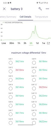
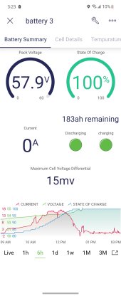
Wanted to share the update of the code to Blynk and screenshots of the app. The shots are after fully charging; note that this battery has a heltec active balancer. you can see it going to work as soc reaches "100" %, according to the bms.

I don't make a habit of changing that high. I wanted to test the new hybrid inverter and active balancer
 

Attachments

  • Screenshot_20220402-152336_Blynk IoT.jpg
    Screenshot_20220402-152336_Blynk IoT.jpg
    118.8 KB · Views: 28
  • Screenshot_20220402-152328_Blynk IoT.jpg
    Screenshot_20220402-152328_Blynk IoT.jpg
    130.1 KB · Views: 27
jbatx, where is the best source in your experience for the heltec products? I see they also have an interesting reasonably costed physical display for individual cell voltages. https://heltec-bms.com/ Do you buy direct or is there someone that stocks them in usa?

That is excellent and exciting work you are doing with blynk!
I bought mine off of Amazon. ...That's the limit of my experience buying heltec stuff
 
I ordered 5 of the boards. They didn't add the mosfets and shipped them out. ...I should have paid more attention to the "fine print". @Porch
 
Hi,
I am Henk and I live in the Netherlands. I stumbled om this thread today and I am verry interested. I build a lifepo4 battery for my rv ( 8 cells, 2p4s) and use a jbd bms (same as overkill).I have used this library: https://github.com/vagueDirector/ArduinoXiaoxiangSmartBMSDisplay from overkill website and adapted it to works with a nodemcu that sends the data to Hivemq (Mosquito service in the cloud). From there I use Node Red and Grafana/influx to display the data. That works sort off, but has some bugs and limitations. I randomly get read errors which I have to filter out and I cannot change the charge / discharge status.
I'd like to build a new interface based on the pcb from Porch and the library made by Jbatx. The library I can download from github but how do I get the PCB?
@ Porch could you sent me the information how to buy them or have them made?
Thanks,
Henk
It was designed on EasyEDA. If you have an account there the project can be shared. However, that design uses a fet that is totally unavailable anywhere these days... supply chain, chip shortage. If you order it, they'll happily build it missing the fet... which makes it useless.

A friend is designing a new one and once it's working I'll make the design available
...also, furtrader has a new version of the overkill library that appears to enable more writes. I have not used it at all
 
Hi,
Thanks for the reply. So I'll have to wait for the new design. ?. I will try the new library of furtrader.
The one i am using now is not very good. It gives a lot off read errors wich I had to filter out.
 
Hi
I am trying to use the bms library of furtrader ( https://github.com/FurTrader/Overkill-Solar-BMS_2-Arduino-Library) but get a problem. When I run one of the examples for instance to get the pack voltage it is not consequent. It alternates between zero volt as packvoltage then one or two times the real packvoltage of 13.34 volt then some times zero and so on. I cannot see why this happens. When I call the debug() routine it gives the same behavior. It alternates between giving the right data like Voltage, current and temp and just zero's.
I use a 150 A jdb-bms with a nodemcu esp8266. Can this be caused by the nodemcu instead of an Arduino mega?. Anny suggestions how to solve this?
Maybe a link to a ino that does work on an esp8266.?

This is my code:

#include "bms2.h"

#include <SoftwareSerial.h>
SoftwareSerial MySoftSerial(2, 4); // RX (d2 wit), TX (d4 -geel), gnd op gnd//Serial voor de BMS
#define Serial2 MySoftSerial
OverkillSolarBms2 bms = OverkillSolarBms2();

//global variables
uint32_t last_update;
float celvoltage=0;
uint32_t timestamp_1000ms = 0;

void setup() {
Serial.begin(115200);
Serial2.begin(9600);
bms.begin(&Serial2);
while (!Serial) { // Wait for the debug serial port to initialize
}
while (!Serial2) { // Wait for the BMS serial port to initialize
}
while(1) {
bms.main_task(true);
if (millis() >= 1000) {
break;
}
delay(10);
}
}
void loop() {
// bms.main_task(true);
bms.query_0x03_basic_info();
float voltage= bms.get_voltage();
delay(100);
Serial.print("voltage pack :");
Serial.println(voltage);
// delay(100);
bms.query_0x04_cell_voltages();
delay(600);
for (int i = 0; i <= 3; i++) {
float cellvoltage=(bms.get_cell_voltage(i) *1000);
if (cellvoltage > 0){
Serial.print(i);
Serial.print(" :");
Serial.print((bms.get_cell_voltage(i) *1000), 0);
Serial.println(" :");
cellvoltage=0;
} else {
Serial.println(" * ");
}
}
delay(100);
// bms.debug();
}

This is the output for Voltage Pack and Cell voltage:
voltage pack :13.33
*
*
*
*
voltage pack :0.00
*
*
*
*
voltage pack :13.33
0 :3335 :
1 :3333 :
2 :3333 :
3 :3334 :
voltage pack :13.33
*
*
*
*
voltage pack :0.00
*
etc.etc.
 
Last edited:
Hi
I am trying to use the bms library of furtrader ( https://github.com/FurTrader/Overkill-Solar-BMS_2-Arduino-Library) but get a problem. When I run one of the examples for instance to get the pack voltage it is not consequent. It alternates between zero volt as packvoltage then one or two times the real packvoltage of 13.34 volt then some times zero and so on. I cannot see why this happens. When I call the debug() routine it gives the same behavior. It alternates between giving the right data like Voltage, current and temp and just zero's.
I use a 150 A jdb-bms with a nodemcu esp8266. Can this be caused by the nodemcu instead of an Arduino mega?. Anny suggestions how to solve this?
Maybe a link to a ino that does work on an esp8266.?

This is my code:

#include "bms2.h"

#include <SoftwareSerial.h>
SoftwareSerial MySoftSerial(2, 4); // RX (d2 wit), TX (d4 -geel), gnd op gnd//Serial voor de BMS
#define Serial2 MySoftSerial
OverkillSolarBms2 bms = OverkillSolarBms2();

//global variables
uint32_t last_update;
float celvoltage=0;
uint32_t timestamp_1000ms = 0;

void setup() {
Serial.begin(115200);
Serial2.begin(9600);
bms.begin(&Serial2);
while (!Serial) { // Wait for the debug serial port to initialize
}
while (!Serial2) { // Wait for the BMS serial port to initialize
}
while(1) {
bms.main_task(true);
if (millis() >= 1000) {
break;
}
delay(10);
}
}
void loop() {
// bms.main_task(true);
bms.query_0x03_basic_info();
float voltage= bms.get_voltage();
delay(100);
Serial.print("voltage pack :");
Serial.println(voltage);
// delay(100);
bms.query_0x04_cell_voltages();
delay(600);
for (int i = 0; i <= 3; i++) {
float cellvoltage=(bms.get_cell_voltage(i) *1000);
if (cellvoltage > 0){
Serial.print(i);
Serial.print(" :");
Serial.print((bms.get_cell_voltage(i) *1000), 0);
Serial.println(" :");
cellvoltage=0;
} else {
Serial.println(" * ");
}
}
delay(100);
// bms.debug();
}

This is the output for Voltage Pack and Cell voltage:
voltage pack :13.33
*
*
*
*
voltage pack :0.00
*
*
*
*
voltage pack :13.33
0 :3335 :
1 :3333 :
2 :3333 :
3 :3334 :
voltage pack :13.33
*
*
*
*
voltage pack :0.00
*
etc.etc.
get_cell_voltage returns a float value, but you are multiplying by an integer and then casting as a float. That's probably not the issue, because you sometimes get non-zero values, but I would add a decimal point to the "1000" so that the compiler forces it to a floating point multiply.

If you do debug, do you get the message "Got an 0x04 Cell Voltage msg" before you read the cell voltages? In the code, it should print that if it got a valid message back from the BMS. It sets the values to zero between reads, so if you do a read and didn't get a valid input from the BMS, it would return zeros for the cell voltages. It's always dicey to read someone else's code, but that's what I see.
 
I use basicly the example from the library. I only changed current to volt and added some print commands.
I do not see the message. Which code do I need to see it?
 
So I run it with all the print commands working. If I get the message "10:49:58.670 -> >> [WAIT_FOR_STOP_BYTE]: Got an 0x04 Cell Voltage msg" the output is populated. Only the BMS name field is (mostly) empty. When the message is not there I get empty fileds or partly filled. Then mostly the cellvoltage is missing.
See below for example output:

After a lot of times output like this:

11:6:32.808 -> >> [WAIT_FOR_DATA]: F0, rx_data_index=
11:6:32.808 -> >> [WAIT_FOR_DATA]: 0, rx_data_index=
11:6:32.808 -> >> [WAIT_FOR_DATA]: 2C, rx_data_index=
11:6:32.808 -> >> [WAIT_FOR_DATA]: D5, rx_data_index=
11:6:32.841 -> >> [WAIT_FOR_DATA]: 0, rx_data_index=
11:6:32.841 -> >> [WAIT_FOR_DATA]: 42, rx_data_index=
11:6:32.841 -> >> [WAIT_FOR_DATA]: 59, rx_data_index=
11:6:32.874 -> >> [WAIT_FOR_DATA]: 3, rx_data_index=
11:6:32.874 -> >> [WAIT_FOR_DATA]: 4, rx_data_index=
11:6:32.874 -> >> [WAIT_FOR_DATA]: 3, rx_data_index=
11:6:32.874 -> >> [WAIT_FOR_DATA]: B, rx_data_index=
11:6:32.874 -> >> [WAIT_FOR_DATA]: A4, rx_data_index=
11:6:32.874 -> >> [WAIT_FOR_DATA]: B, rx_data_index=
11:6:32.874 -> >> [WAIT_FOR_DATA]: 9E, rx_data_index=
11:6:32.874 -> >> [WAIT_FOR_DATA]: B, rx_data_index=
11:6:32.874 -> >> [WAIT_FOR_DATA]: 99, rx_data_index=
11:6:32.913 -> >> [WAIT_FOR_CHECKSUM_MSB]:
11:6:32.913 -> >> [WAIT_FOR_CHECKSUM_LSB]:
11:6:32.913 -> >> [WAIT_FOR_STOP_BYTE]: The rx_state is: 0<< DD A5 3 0 FF FD << DD A5 3 0 FF FD 10
11:6:33.486 -> >> [WAIT_FOR_START_BYTE]:
11:6:33.486 -> >> [WAIT_FOR_CMD_CODE]:
11:6:33.486 -> >> [WAIT_FOR_STATUS_BYTE]:
11:6:33.486 -> >> [WAIT_FOR_LENGTH]:
11:6:33.486 -> >> [WAIT_FOR_DATA]: 5, rx_data_index=
11:6:33.486 -> >> [WAIT_FOR_DATA]: 2F, rx_data_index=
11:6:33.486 -> >> [WAIT_FOR_DATA]: FF, rx_data_index=
11:6:33.486 -> >> [WAIT_FOR_DATA]: BB, rx_data_index=
11:6:33.486 -> >> [WAIT_FOR_DATA]: 4C, rx_data_index=
11:6:33.486 -> >> [WAIT_FOR_DATA]: C7, rx_data_index=The rx_state is: 426
11:6:33.520 -> >> [WAIT_FOR_DATA]: 55, rx_data_index=
11:6:33.520 -> >> [WAIT_FOR_DATA]: F0, rx_data_index=
11:6:33.520 -> >> [WAIT_FOR_DATA]: 0, rx_data_index=
11:6:33.520 -> >> [WAIT_FOR_DATA]: 2C, rx_data_index=
11:6:33.520 -> >> [WAIT_FOR_DATA]: D5, rx_data_index=
11:6:33.520 -> >> [WAIT_FOR_DATA]: 0, rx_data_index=
11:6:33.553 -> >> [WAIT_FOR_DATA]: 0, rx_data_index=
11:6:33.553 -> >> [WAIT_FOR_DATA]: 42, rx_data_index=
11:6:33.553 -> >> [WAIT_FOR_DATA]: 59, rx_data_index=
11:6:33.553 -> >> [WAIT_FOR_DATA]: 3, rx_data_index=
11:6:33.553 -> >> [WAIT_FOR_DATA]: 4, rx_data_index=
11:6:33.553 -> >> [WAIT_FOR_DATA]: 3, rx_data_index=
11:6:33.588 -> >> [WAIT_FOR_DATA]: B, rx_data_index=
11:6:33.588 -> >> [WAIT_FOR_DATA]: A4, rx_data_index=
11:6:33.588 -> >> [WAIT_FOR_DATA]: B, rx_data_index=
11:6:33.588 -> >> [WAIT_FOR_DATA]: 9E, rx_data_index=
11:6:33.588 -> >> [WAIT_FOR_DATA]: B, rx_data_index=
11:6:33.588 -> >> [WAIT_FOR_DATA]: 99, rx_data_index=
11:6:33.588 -> >> [WAIT_FOR_CHECKSUM_MSB]:
11:6:33.588 -> >> [WAIT_FOR_CHECKSUM_LSB]:
11:6:33.588 -> >> [WAIT_FOR_STOP_BYTE]: The rx_state is: 0<< DD A5 4 0 FF FC 2
11:6:33.669 -> >> [WAIT_FOR_START_BYTE]:
11:6:33.669 -> >> [WAIT_FOR_CMD_CODE]: The rx_state is: 110
11:6:33.669 -> >> [WAIT_FOR_STATUS_BYTE]:
11:6:33.669 -> >> [WAIT_FOR_LENGTH]:
11:6:33.669 -> >> [WAIT_FOR_DATA]: C, rx_data_index=
11:6:33.669 -> >> [WAIT_FOR_DATA]: F9, rx_data_index=
11:6:33.669 -> >> [WAIT_FOR_DATA]: C, rx_data_index=
11:6:33.702 -> >> [WAIT_FOR_DATA]: F8, rx_data_index=
11:6:33.702 -> >> [WAIT_FOR_DATA]: C, rx_data_index=
11:6:33.702 -> >> [WAIT_FOR_DATA]: F8, rx_data_index=
11:6:33.702 -> >> [WAIT_FOR_DATA]: C, rx_data_index=
11:6:33.702 -> >> [WAIT_FOR_DATA]: F8, rx_data_index=The rx_state is: 53
11:6:33.702 -> >> [WAIT_FOR_CHECKSUM_MSB]:
11:6:33.702 -> >> [WAIT_FOR_CHECKSUM_LSB]:

After a lot of empty datafields this message and fields are mostly filled. Only BMS name is only filled incidential.

11:6:33.702 -> >> [WAIT_FOR_STOP_BYTE]: Got an 0x04 Cell Voltage msg

11:6:33.735 -> The rx_state is: 0==============================================
11:6:33.735 -> Voltage: 13.270 V
11:6:33.735 -> Current: Raw current: -69Scaled current: -0.6900000000-0.690 A
11:6:33.735 -> Balance capacity: 196.550 Ah
11:6:33.735 -> Rate capacity: 220.000 Ah
11:6:33.735 -> Cycle count: 0
11:6:33.735 -> Production Date: 21/6/2022
11:6:33.735 -> Protection Status:
11:6:33.735 -> software_lock_mos: 0
11:6:33.735 -> front_end_detection_ic_error: 0
11:6:33.769 -> short_circuit_protection: 0
11:6:33.769 -> discharge_overcurrent_protection: 0
11:6:33.769 -> charging_overcurrent_protection: 0
11:6:33.769 -> discharge_low_temperature_protection: 0
11:6:33.769 -> discharge_over_temperature_protection:0
11:6:33.769 -> charging_low_temperature_protection: 0
11:6:33.769 -> charging_over_temperature_protection: 0
11:6:33.769 -> whole_pack_undervoltage_protection: 0
11:6:33.769 -> whole_pack_overvoltage_protection: 0
11:6:33.802 -> single_cell_undervoltage_protection: 0
11:6:33.802 -> single_cell_overvoltage_protection: 0
11:6:33.802 -> Software version: 4.2
11:6:33.802 -> State of Charge: 89%
11:6:33.802 -> Discharge MOSFET: ON
11:6:33.802 -> Charge MOSFET: ON
11:6:33.802 -> # of cells: 4
11:6:33.802 -> # of temp sensors: 3
11:6:33.802 -> Temperatures:
11:6:33.802 -> 24.9 deg C
11:6:33.802 -> 24.2 deg C
11:6:33.802 -> 23.7 deg C
11:6:33.802 -> Cell Voltages & Balance Status:
11:6:33.802 -> 3.321V (not balancing)
11:6:33.802 -> 3.320V (not balancing)
11:6:33.836 -> 3.320V (not balancing)
11:6:33.836 -> BMS Name: << DD A5 5 0 FF FB
11:6:34.329 -> ==============================================

And again a lot of empty or partly filled datafields:

11:6:34.329 ->
11:6:34.329 -> << DD A5 3 0 FF FD << DD A5 3 0 FF FD << DD A5 3 0 FF FD << DD A5 4 0 FF FC ==============================================
11:6:36.376 -> Voltage: 0.000 V
11:6:36.376 -> Current: Raw current: 0Scaled current: 0.00000000000.000 A
11:6:36.376 -> Balance capacity: 0.000 Ah
11:6:36.376 -> Rate capacity: 0.000 Ah
11:6:36.376 -> Cycle count: 0
11:6:36.376 -> Production Date: 0/0/2000
11:6:36.376 -> Protection Status:
11:6:36.376 -> software_lock_mos: 0
11:6:36.376 -> front_end_detection_ic_error: 0
11:6:36.376 -> short_circuit_protection: 0
11:6:36.410 -> discharge_overcurrent_protection: 0
11:6:36.410 -> charging_overcurrent_protection: 0
11:6:36.410 -> discharge_low_temperature_protection: 0
11:6:36.410 -> discharge_over_temperature_protection:0
11:6:36.410 -> charging_low_temperature_protection: 0
11:6:36.410 -> charging_over_temperature_protection: 0
11:6:36.410 -> whole_pack_undervoltage_protection: 0
11:6:36.410 -> whole_pack_overvoltage_protection: 0
11:6:36.410 -> single_cell_undervoltage_protection: 0
11:6:36.443 -> single_cell_overvoltage_protection: 0
11:6:36.443 -> Software version: 0.0
11:6:36.443 -> State of Charge: 0%
11:6:36.443 -> Discharge MOSFET: OFF
11:6:36.443 -> Charge MOSFET: OFF
11:6:36.443 -> # of cells: 0
11:6:36.443 -> # of temp sensors: 0
11:6:36.443 -> Temperatures:
11:6:36.443 -> Cell Voltages & Balance Status:
11:6:36.443 -> BMS Name: << DD A5 5 0 FF FB 7
11:6:36.475 -> >> [WAIT_FOR_START_BYTE]:
11:6:36.475 -> >> [WAIT_FOR_CMD_CODE]:
11:6:36.475 -> >> [WAIT_FOR_STATUS_BYTE]:
11:6:36.475 -> >> [WAIT_FOR_LENGTH]:
11:6:36.475 -> >> [WAIT_FOR_DATA]: 4A, rx_data_index=
11:6:36.475 -> >> [WAIT_FOR_DATA]: 42, rx_data_index=
11:6:36.475 -> >> [WAIT_FOR_DATA]: 44, rx_data_index=The rx_state is: 422
 
Back
Top