So, after buying a bunch of random parts for my HVDC Franken-Inverter project and then putting it on the backburner for college, I'm finally done with classes and have ~1 month free before next semester. So time to get cranking!
I was daydreaming a bit about the inverter, and decided it would probably be a bit easier to work on the solar charger part. After all, it's pretty simple operation.
While I was planning the initial inverter (Using the Toshiba MG300J2YS40 300A-600V IGBT bricks, which got for $15 a pop, but left behind for a set of monstrous Infineon FF1000R17IE4 1400A-1700V bricks) I remembered I had also purchased a couple of these gate drivers:
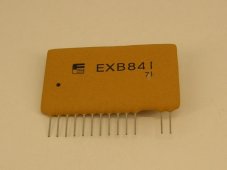
They are Fuji EXB841 IGBT drivers. Rated to drive up to 400A modules at up to 40kHz. Only cost around $4 each. Given that they're from the same era ~early 2000's, I figured they'd be a decent match with the MG300J2YS40's. And they are. The main reason why I didn't end up using these in the inverter part is b/c they are too weak to drive the large bricks I decided to go with.
So basically I was just looking through my component trays and realized I could just pair these up and make an Arduino (ESP32) PWM controller.
As I started writing the code I realized that you can do SO MANY things with a PWM controller by only changing a few things.
So I kind of deviated a little bit. I started adding options to my code, so that you can set different 'Modes' for the controller, such as Variable PSU, Fixed PSU, and Solar Charging. Also picked a 5000Hz carrier frequency as that's fast enough to not be loud and super noisy (in both terms of the word), but slow enough so that the gate isn't working overtime.
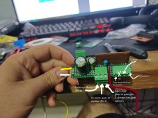
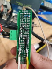
To be able to use the driver properly I figured I might as well just make a little breadboard. I was surprised by how little external circuitry it needed. There's only 4 other components on the board:
-a 2200uF capacitor on the 20v bus (I literally have a bag of them, I understand its overkill but I enjoy putting big capacitors on things)
-a 470uF capacitor placed parallel to the negative voltage drive of the driver (It's recommended in the EXB841 manual)
-6.8ohm 2w gate resistor. Manual for the EXB841 recommends 8.2ohm but I later tested with another in series to make 8.2 and it made no difference in ringing.
-200ohm resistor for the built-in optocoupler, to run it off of the ~3.27 volts from the ESP32 at ~11mA.
I put these terminal connectors I had laying around so I could make it at least somewhat detachable for when I inevitably have to move wires around.
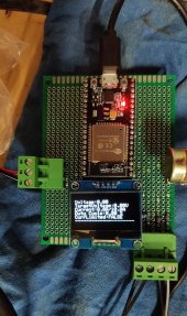
I then used one of those proto-boards to set up my ESP32 with an INA226 Current & voltage sensor, a 1.3" OLED display for troubleshooting, and a potentiometer to input controls.
I then set it up, USB powering the ESP32, my adjustable bench power supply powering the IGBT driver with 20v, and a 12v server PSU as my power source to be controlled.
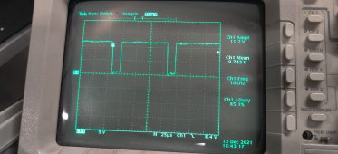
At first I used a 12V 5A halogen lamp for testing, and used the capacitors from the inverter as an output 'filter'. Although it wasn't doing much of that haha. As expected, nothing really worked properly. My code for AVR(automatic voltage regulation) was a bit exaggerated, and struggled to maintain low voltages. AND HOLY noise... Everytime the IGBT started purring, the IIC display connected to the breadboard went HAYWIRE. Spamming all sorts of ancient hieroglyphs and perhaps some alien alphabets in there as well. I connected my scope to the Emmiter-Gate, and there was the problem. A LOT of ringing.
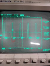
It was so bad that it was enough to re-activate the gate twice before dying down.
I stole one of the 3.0uF Snubber capacitors from the inverter and put it on the power supply side of the IGBT. It helped, there was now much less noise in the system (screen wasn't spazzing out anymore, current and voltage readings from the INA226 were MUCH more stable) but there was still enough gate ringing to cause problems.
So I started troubleshooting. First I assumed it was the gate drive, but after messing around with different gate resistors and making ZERO difference in the ringing, I went further back, to the output pin of the ESP32. And to my surprise, it was also ringing, which was in turn causing the IGBT driver to mimic the ringing and cause an excessive ringing. After some messing around, I tried turning off the 12v supply connected to the IGBT, and the signals cleaned up COMPLETELY. They were perfect. Back to square 1.
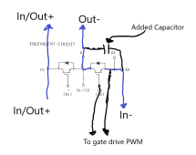
I then started messing around with a 470uF electrolytic cap, placing it in different parts of the circuit, and found that placing it right across the collector and emitter of the switching transistor (the module has 2 transistors, B1 is left open and used only as a diode) worked best. There was a HUGE decrease in ringing.
Here's a drawing of where I placed it.
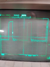
Not only was the ringing drastically decreased, but the IGBT is now heating up much less. With a 160W draw (at the wall, by the PSU, take off maybe 15% for efficiency) in total say 136w, calculating at 12.5V of the PSU totals around ~10.88A flowing through the IGBT. Before the capacitor, the IGBT with the little heatsink just sitting on the table reached equilibrium at around 60C at the base, and around 55C at the heatsink.
After the capacitor, I felt confident and bumped up the load to 200w. Again, assuming 85% PSU efficiency equals to 170w at 12.5V, which means ~13.6A were flowing through the IGBT. And it was running significantly colder, staying under 50C throughout testing, which I'm quite pleased with. With the size of the heatsink and not having a fan, or thermal paste (used double sided thermal tape, it's not that good) it was nice to see. I'm sure with a proper heatsink and fan, I'd be able to push 100A continuous through this without issues, with a pretty large overhead.
The beautiful thing about IGBTs like this are the voltage ratings. Like right now, 13.6A at 12v isn't much power at all. But if this were a 320vdc bus connected to 400v of solar panels, you could literally pass 320*13.6=4.3kW of power in the state that it is right now, without even using a fan. At 100A, over 30kW!
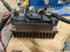
Sorry for how messy/ratchet everything is but I literally cobbled this together in like 2 hours. It's a proof of concept but I will definitely be polishing the code as well as making proper bus bars for it and adding proper filtering. With 2 snubbers the rest of the ringing should be minimized.
As of now, I've only really done the voltage portion of the controller, meaning that the variable PSU works halfway, as I haven't implemented current controls yet, and Fixed PSU works pretty good. The charger portion works but it's dumb, as in it basically just locks at 100% duty cycle until it reaches the target voltage and if it starts dropping, starts modulating at just the right duty cycle to keep the voltage at the target voltage. There's no phases or soaking or anything like that.
I just need to configure the current monitoring, right now I'm using an INA226 with a 750A 75mA shunt. (Yes, seven-hundred-fifty amps) as that's what I have on hand ATM. I have a 100A shunt coming sometime in the future to make measurements much more accurate, as the 750A shunt is understandably fidgety at low currents.
The IGBT gate driver has a built-in overcurrent detection system, which I have to figure out how it works, since the manual is very vague about it for some reason. Once I do that I just have to set up an interrupt in the ESP32 to shut down if and when such an event is triggered.
I also have a pair of EV200AAANA 500A 900V relays/contactors coming in, which I plan to use one for this charger. This will be extremely useful in situations where all solar power input is needed, where the PWM would just be locked at 100%, like every morning for example. The idea is that it will just bypass the IGBT and connect the solar straight to the output, until the target voltage is reached, in which case it will drop the contactor and begin working on PWM again. The idea behind it is to avoid the innate power losses in the IGBT. Even when IGBT's are fully on, they have a voltage drop of around 1.5-2V. Meaning, at 100A for example, it will be dissipating more than 200W+ of power, if not more (the drop slightly increases with current, my IGBTs manuals don't have the graph for it though. Which, if you consider you're charging 100A at 320v, that's over 30kW, so you can say 99% efficiency is still pretty good, but at lower voltages it it starts to add up. For example, if I had a 48v system charging at the same 100A, that's 4800w, but you still lose more than 200w at the IGBT. By using a contactor you save all that power.
In terms of MPPT VS PWM at these high voltages, there's really not much point in going MPPT. MPPT is for low voltages using higher voltage panels. In this case, the MAX open circuit voltage of whatever solar circuit I have connected must be less than 600V. That leaves room for a ~92S lithium battery hovering between 310V (minimum required to make to 220vac) (@3.4vpc) and 380v (@4.15vpc) charged. Plenty of headroom.
But anyways, still plenty of work to be done, but at least as a proof of concept works. Without proper filtering was able to maintain a ~+-400mv ripple at low duty cycles. Good enough for me. Might make a video soon in a couple of days if I make significant progress.
I was daydreaming a bit about the inverter, and decided it would probably be a bit easier to work on the solar charger part. After all, it's pretty simple operation.
While I was planning the initial inverter (Using the Toshiba MG300J2YS40 300A-600V IGBT bricks, which got for $15 a pop, but left behind for a set of monstrous Infineon FF1000R17IE4 1400A-1700V bricks) I remembered I had also purchased a couple of these gate drivers:

They are Fuji EXB841 IGBT drivers. Rated to drive up to 400A modules at up to 40kHz. Only cost around $4 each. Given that they're from the same era ~early 2000's, I figured they'd be a decent match with the MG300J2YS40's. And they are. The main reason why I didn't end up using these in the inverter part is b/c they are too weak to drive the large bricks I decided to go with.
So basically I was just looking through my component trays and realized I could just pair these up and make an Arduino (ESP32) PWM controller.
As I started writing the code I realized that you can do SO MANY things with a PWM controller by only changing a few things.
So I kind of deviated a little bit. I started adding options to my code, so that you can set different 'Modes' for the controller, such as Variable PSU, Fixed PSU, and Solar Charging. Also picked a 5000Hz carrier frequency as that's fast enough to not be loud and super noisy (in both terms of the word), but slow enough so that the gate isn't working overtime.


To be able to use the driver properly I figured I might as well just make a little breadboard. I was surprised by how little external circuitry it needed. There's only 4 other components on the board:
-a 2200uF capacitor on the 20v bus (I literally have a bag of them, I understand its overkill but I enjoy putting big capacitors on things)
-a 470uF capacitor placed parallel to the negative voltage drive of the driver (It's recommended in the EXB841 manual)
-6.8ohm 2w gate resistor. Manual for the EXB841 recommends 8.2ohm but I later tested with another in series to make 8.2 and it made no difference in ringing.
-200ohm resistor for the built-in optocoupler, to run it off of the ~3.27 volts from the ESP32 at ~11mA.
I put these terminal connectors I had laying around so I could make it at least somewhat detachable for when I inevitably have to move wires around.
I then used one of those proto-boards to set up my ESP32 with an INA226 Current & voltage sensor, a 1.3" OLED display for troubleshooting, and a potentiometer to input controls.
I then set it up, USB powering the ESP32, my adjustable bench power supply powering the IGBT driver with 20v, and a 12v server PSU as my power source to be controlled.
At first I used a 12V 5A halogen lamp for testing, and used the capacitors from the inverter as an output 'filter'. Although it wasn't doing much of that haha. As expected, nothing really worked properly. My code for AVR(automatic voltage regulation) was a bit exaggerated, and struggled to maintain low voltages. AND HOLY noise... Everytime the IGBT started purring, the IIC display connected to the breadboard went HAYWIRE. Spamming all sorts of ancient hieroglyphs and perhaps some alien alphabets in there as well. I connected my scope to the Emmiter-Gate, and there was the problem. A LOT of ringing.

It was so bad that it was enough to re-activate the gate twice before dying down.
I stole one of the 3.0uF Snubber capacitors from the inverter and put it on the power supply side of the IGBT. It helped, there was now much less noise in the system (screen wasn't spazzing out anymore, current and voltage readings from the INA226 were MUCH more stable) but there was still enough gate ringing to cause problems.
So I started troubleshooting. First I assumed it was the gate drive, but after messing around with different gate resistors and making ZERO difference in the ringing, I went further back, to the output pin of the ESP32. And to my surprise, it was also ringing, which was in turn causing the IGBT driver to mimic the ringing and cause an excessive ringing. After some messing around, I tried turning off the 12v supply connected to the IGBT, and the signals cleaned up COMPLETELY. They were perfect. Back to square 1.
I then started messing around with a 470uF electrolytic cap, placing it in different parts of the circuit, and found that placing it right across the collector and emitter of the switching transistor (the module has 2 transistors, B1 is left open and used only as a diode) worked best. There was a HUGE decrease in ringing.

Here's a drawing of where I placed it.

Not only was the ringing drastically decreased, but the IGBT is now heating up much less. With a 160W draw (at the wall, by the PSU, take off maybe 15% for efficiency) in total say 136w, calculating at 12.5V of the PSU totals around ~10.88A flowing through the IGBT. Before the capacitor, the IGBT with the little heatsink just sitting on the table reached equilibrium at around 60C at the base, and around 55C at the heatsink.
After the capacitor, I felt confident and bumped up the load to 200w. Again, assuming 85% PSU efficiency equals to 170w at 12.5V, which means ~13.6A were flowing through the IGBT. And it was running significantly colder, staying under 50C throughout testing, which I'm quite pleased with. With the size of the heatsink and not having a fan, or thermal paste (used double sided thermal tape, it's not that good) it was nice to see. I'm sure with a proper heatsink and fan, I'd be able to push 100A continuous through this without issues, with a pretty large overhead.
The beautiful thing about IGBTs like this are the voltage ratings. Like right now, 13.6A at 12v isn't much power at all. But if this were a 320vdc bus connected to 400v of solar panels, you could literally pass 320*13.6=4.3kW of power in the state that it is right now, without even using a fan. At 100A, over 30kW!

Sorry for how messy/ratchet everything is but I literally cobbled this together in like 2 hours. It's a proof of concept but I will definitely be polishing the code as well as making proper bus bars for it and adding proper filtering. With 2 snubbers the rest of the ringing should be minimized.
As of now, I've only really done the voltage portion of the controller, meaning that the variable PSU works halfway, as I haven't implemented current controls yet, and Fixed PSU works pretty good. The charger portion works but it's dumb, as in it basically just locks at 100% duty cycle until it reaches the target voltage and if it starts dropping, starts modulating at just the right duty cycle to keep the voltage at the target voltage. There's no phases or soaking or anything like that.
I just need to configure the current monitoring, right now I'm using an INA226 with a 750A 75mA shunt. (Yes, seven-hundred-fifty amps) as that's what I have on hand ATM. I have a 100A shunt coming sometime in the future to make measurements much more accurate, as the 750A shunt is understandably fidgety at low currents.
The IGBT gate driver has a built-in overcurrent detection system, which I have to figure out how it works, since the manual is very vague about it for some reason. Once I do that I just have to set up an interrupt in the ESP32 to shut down if and when such an event is triggered.
I also have a pair of EV200AAANA 500A 900V relays/contactors coming in, which I plan to use one for this charger. This will be extremely useful in situations where all solar power input is needed, where the PWM would just be locked at 100%, like every morning for example. The idea is that it will just bypass the IGBT and connect the solar straight to the output, until the target voltage is reached, in which case it will drop the contactor and begin working on PWM again. The idea behind it is to avoid the innate power losses in the IGBT. Even when IGBT's are fully on, they have a voltage drop of around 1.5-2V. Meaning, at 100A for example, it will be dissipating more than 200W+ of power, if not more (the drop slightly increases with current, my IGBTs manuals don't have the graph for it though. Which, if you consider you're charging 100A at 320v, that's over 30kW, so you can say 99% efficiency is still pretty good, but at lower voltages it it starts to add up. For example, if I had a 48v system charging at the same 100A, that's 4800w, but you still lose more than 200w at the IGBT. By using a contactor you save all that power.
In terms of MPPT VS PWM at these high voltages, there's really not much point in going MPPT. MPPT is for low voltages using higher voltage panels. In this case, the MAX open circuit voltage of whatever solar circuit I have connected must be less than 600V. That leaves room for a ~92S lithium battery hovering between 310V (minimum required to make to 220vac) (@3.4vpc) and 380v (@4.15vpc) charged. Plenty of headroom.
But anyways, still plenty of work to be done, but at least as a proof of concept works. Without proper filtering was able to maintain a ~+-400mv ripple at low duty cycles. Good enough for me. Might make a video soon in a couple of days if I make significant progress.


