diy solar

diy solar

Array to CC wiring question

It is a bit of a toss up depending on the actual shade.


I would tend to skip the fuses. Fairly low power and for some fault to occur just right to cause trouble would be exceedingly rare.
Length of wire doesn't matter for amperage rating. Amps heat a particular gauge of wire by some number of degrees.
Length matters for voltage drop. That may start to matter for 3 or 4 panels in parallel, but mostly I don't worry about it on PV side.
I care about voltage drop charge controller to battery, battery to inverter, AC wires inverter to load.

On a vehicle? Just size the PV wires to carry the current, without regard to length.
The reason I asked this is because of the windy nation wire ampacity chart shown.

If wire length doesn’t matter regarding amperage,10AWG should be sufficient for inter-panel wiring? (~39 amps)

Or is 8AWG necessary for ~39 amps? (inter-panel wiring)

(these panels have 12AWG leads from the factory)

1619062908149.jpeg (mine is a 24 volt system and the array makes 38.96 amps wired 4p2s)


(pg. 12)
 
Last edited:
#12 is fine for series connections. Once you go parallel the ampacity needs to be sufficient to carry max power. At 40 amps I would be at #8 wire and maybe #6. With so much parallel you may want to have a combiner box and use some fat wire to the controller. The MC4 parallel connectors I see are rated 30 amps max. I think the #8 MC4 wire would be to reduce voltage drop and may not increase ampacity of the connectors to be over 30 amps. Or have multiple runs down to the controller where they can be combined. Or use two controllers.

What controller are you using? Have you given any thought to running all in series?
 
Last edited:
#12 is fine for series connections. Once you go parallel the ampacity needs to be sufficient to carry max power. At 40 amps I would be at #8 wire and maybe #6. With so much parallel you may want to have a combiner box and use some fat wire to the controller. The MC4 parallel connectors I see are rated 30 amps max. I think the #8 MC4 wire would be to reduce voltage drop and may not increase ampacity of the connectors to be over 30 amps. Or have multiple runs down to the controller where they can be combined.
Yeah, it looks like #8 wire is necessary for 40 amps. These Trina panels actually have TS4 connectors instead of MC4. The TS4 connectors designed to fit #12 wire are rated for 41 amps.


The issue is they don’t make TS4 branch connectors (‘Y’) for #8 wire.

The largest wire they make them for is #10.

So, I’m not sure what to do to connect panel to panel.

I might not be able to use 8 panels in 4p2s and might have to only use 6 panels in 3p2s?

And yes, combiner box at the array landing transitioning to some #4 in conduit is what I want to run the ~50 feet to charge controller landing with.

Thoughts on this quandary?
 
Use 10 awg "Y" for each pair of strings, and run 10 awg to the charge controller (or a box) where two sets of wire come together to put all four strings in parallel. Either two 10 awg all the way to the controller (multiple runs like time2roll said), or join somewhere and use at least 8 awg after that.
 
Use 10 awg "Y" for each pair of strings, and run 10 awg to the charge controller (or a box) where two sets of wire come together to put all four strings in parallel. Either two 10 awg all the way to the controller (multiple runs like time2roll said), or join somewhere and use at least 8 awg after that.
10AWG only seems rated for 30 amps though and with 2 groups of 4 panels in parallel and those in series is still 40 amps.
The only issue with using 8AWG here is TS4 connectors are only made to fit up to a 10AWG.

Even if I used 2 sets of 10AWG, it would still exceed the 30 amp rating of 10AWG.
 
10AWG only seems rated for 30 amps though and with 2 groups of 4 panels in parallel and those in series is still 40 amps.
The only issue with using 8AWG here is TS4 connectors are only made to fit up to a 10AWG.

Even if I used 2 sets of 10AWG, it would still exceed the 30 amp rating of 10AWG.

"2 groups of 4 panels in parallel and those in series"
We call that 4p2s, because 4 panels are connected in parallel before being connected in series.

Try 2s4p, 4 pairs of 2 panels in series and those in parallel. Except that ends up with 40A.
So 2s2p, 2 pairs of 2 panels in series and those in parallel, for 20A, with its own 10 AWG wires. Then a second set with its own 10 AWG wires.

If panels approximately 10A and you connect 4 panels in parallel that is 40A.
If you connect 4 panels in series (which would be too high a voltage for your charge controller) that is 10A (and 4x the voltage)
If you connect 4 panels series/parallel 2s2p that is 20A (and 2x the voltage), good for 10 AWG and good for your charge controller.

With a pair of 10 AWG TS4 (or MC4) cables you can extend a "Y" connector with 2s2p panels back to your charge controller.
A second set like that would connect the remaining 4 panels.
The two 10 AWG wires for positive connect at charge controller, as do the two for negative. Each wire nominally carries 20A.

Alternatively, have a junction box where the two "Y" connectors for positive join to an 8 AWG wire, same for the two "Y" connectors for negative.
Or, instead of "Y" connectors have four TS4 (or MC4) pigtails join inside the box to the 8 AWG wire. (Which is how one of my ground arrays is wired.)

With the 4p arrangement, you should have a fuse per string because if a short develops in one string (which has 12 AWG to the panel), the other three panels would put 30A into it. These can be MC4 fuse holder, but your panels have TS4? If such fuse holders aren't available, either MC4 to TS4 adapters, or a junction box with fuse holders and TS4 pigtails.
Yes, these Trina panels have TS4 connectors on 12AWG from factory.

It’s looking like 4p2s is prohibitive.

I’m going to try it in 3p2s configuration.

Is it overkill to use 10AWG to connect the solar panels together?

In other words, because the individual 400 watt solar panels (isc 9.74) are supplied from the factory with 12AWG, is there a reason to go larger than this where wiring the solar panels together?
 
The panels have 12 awg which is good for 20A, sufficient for their 9.74A Isc, and each string should be protected with 20A fuse when several are connected in parallel. The fuse-protected strings are 12 awg, and a larger wire carries the combined current from several strings.

If you connect several in series, 12 awg is fine unless it is such a long wire that IR drop would be excessive.
If you connect even two in parallel, should be 10 awg to handle the higher current.
If more than two in parallel, a wire which carries the current of 3 or more strings should be larger than 10 awg, possibly 8 awg or even larger.

Rather than 4p2s, consider 2s4p.
That could be done as 2x 2s2p, each 2s2p with its own pair of 10 awg wired back to the charge controller
Or 2s4p joined in a junction box, and one pair of heavier wires back to the controller.

I use 12 awg for each string, coming back to a junction box. I have fuses in the box, and either 6 awg or 8 awg (depending on how many strings) from junction box to inverter.
‘If more than two in parallel, a wire which carries the current of 3 or more strings should be larger than 10 awg, possibly 8 awg or even larger.’

Yes, definitely going to use 6AWG to make the ~50’ run from array to charge controller.

The wire used from each solar panel to the next solar panel though is where I’m not sure about wire size.

In the 3p2s context, using the TS4 ‘y’ branch connectors requires separate wire other than the 4’6” 12AWG factory wires.

Is using 10AWG for this ‘inter-panel’ wiring where a max of 29.22 amps of current would be produced by the entire array of 6 panels be effective, or would the 12AWG factory wire limit the effect of higher amperage rating of 10AWG?

I’m not sure how the max current of the total array interacts with ‘seperate’ ‘inter-panel’ wiring, vs. the factory wire that’s on each panel..

Is a 3p2s even allowable given the 12AWG factory panel wire?
 
‘If more than two in parallel, a wire which carries the current of 3 or more strings should be larger than 10 awg, possibly 8 awg or even larger.’

Yes, definitely going to use 6AWG to make the ~50’ run from array to charge controller.

The wire used from each solar panel to the next solar panel though is where I’m not sure about wire size.

The 12 awg wires that come with the panel are fine. If you connected panels in series (e.g. 2s4p) you could plug the panels into each other, or extend between the or before or after them with 12 awg. Only after 2 or more strings join in parallel do you need larger gauge.

In the 3p2s context, using the TS4 ‘y’ branch connectors requires separate wire other than the 4’6” 12AWG factory wires.

If you wire 3p2s or 4p2s, you're putting 3 or 4 panels in parallel. Each panel should have a fuse. After joining, they should have 8 awg or 6 awg. After joining they should not go through an MC4 or TS4 connector (unless you find a connector with sufficient current rating.)

Doing 3p2s rather than 2s3p means you have to deal with the larger gauge in the middle, not just at the ends.

Is using 10AWG for this ‘inter-panel’ wiring where a max of 29.22 amps of current would be produced by the entire array of 6 panels be effective, or would the 12AWG factory wire limit the effect of higher amperage rating of 10AWG?

I’m not sure how the max current of the total array interacts with ‘seperate’ ‘inter-panel’ wiring, vs. the factory wire that’s on each panel..

Each factory wire carries only the current of that panel. In case of a fault, the current backfed into it, which is why a fuse.
If you wire 3p2s, then if some panels go open circuit or are unplugged, all the panels in the other 3p group force their current through it, so it needs a fuse. There is a fair chance the fuse doesn't blow, but the diode burns up instead.

Is a 3p2s even allowable given the 12AWG factory panel wire?

You can protect the wires with a fuse per panel. But like I said I'm concerned about the bypass diodes. Some brands, those can hardly handle the current of a single panel, certainly not the current of multiple panels.

I still recommend 2s4p.
 
The 12 awg wires that come with the panel are fine. If you connected panels in series (e.g. 2s4p) you could plug the panels into each other, or extend between the or before or after them with 12 awg. Only after 2 or more strings join in parallel do you need larger gauge.


If you wire 3p2s or 4p2s, you're putting 3 or 4 panels in parallel. Each panel should have a fuse. After joining, they should have 8 awg or 6 awg. After joining they should not go through an MC4 or TS4 connector (unless you find a connector with sufficient current rating.)

Doing 3p2s rather than 2s3p means you have to deal with the larger gauge in the middle, not just at the ends.


Each factory wire carries only the current of that panel. In case of a fault, the current backfed into it, which is why a fuse.
If you wire 3p2s, then if some panels go open circuit or are unplugged, all the panels in the other 3p group force their current through it, so it needs a fuse. There is a fair chance the fuse doesn't blow, but the diode burns up instead.


You can protect the wires with a fuse per panel. But like I said I'm concerned about the bypass diodes. Some brands, those can hardly handle the current of a single panel, certainly not the current of multiple panels.

I still recommend 2s4p.
1619474878391.jpeg
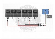
Is this the type of series/parallel connection you’re suggesting, only with another series string of 2 solar panels in the picture and 2 sets of wires from the array to charge controller instead of 1?
 
Is this the type of series/parallel connection you’re suggesting, only with another series string of 2 solar panels in the picture and 2 sets of wires from the array to charge controller instead of 1?

Yes, that shows 2s3p. It uses a pair of 3Y connectors.

I'm suggesting wiring 4 panels like that for 2s2p with a pair of 2Y connectors. Then making another copy just like it, with its own wires going all the way to the charge controller.
Also adding 4 fuses.
 
Yes, that shows 2s3p. It uses a pair of 3Y connectors.

I'm suggesting wiring 4 panels like that for 2s2p with a pair of 2Y connectors. Then making another copy just like it, with its own wires going all the way to the charge controller.
Also adding 4 fuses.
1619544898440.jpeg
Ok, I’m trying to get your 2s4p suggestion exactly right.

1. What gauge wires should the non-factory (‘inter-panel’) wires shown in the diagram be, 12AWG or 10AWG?

2. Where exactly do the 4, 20A fuses go?

3. What is the next connection to make on the way to charge controller to end up with 100V and 40A at the charge controller?

(thanks for your patience and your help Hedges, greatly appreciated man)
 
12 awg is good between panel and to the 2Y connectors. Each length carries 10A.

After the 2Y connectors, 10 awg would carry 20A to the charge controller. It that is really 20A, then 20A x 1.56 = 31A which is more than the 30A we're supposed to fuse 10 awg at, but I wouldn't be concerned if not being inspected. I know it has 40A ampacity.

Both runs of 10 awg would joint at the charge controller. 20 + 20 = 40A into charge controller.

The four fuses would go between PV panel positive and 2Y connector.
So the drawing is good, just need to add fuses.
 
Back
Top