diy solar

diy solar

Array to CC wiring question

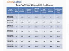
8 AWG, supporting 35A @ 82 volts V(mp) on a 70 foot run loses around 4.6% in wiring losses (AKA "Voltage Drop", the SCC receives only 78.1 Volts of difference.) 6 AWG would lose about 2.9%, at rated panel output. The number of strands creates small differences in these figures. I don't know if you need type UF, or whether everyday building wire will be OK. 70 feet seems like a kinda long run.
I looked at the price of ~ 280 ft. of both #8 and #6 cable and it’s about the same price as another panel.
I also checked the availability of these same panels and they are available still.
Would you prefer seeing 1 extra 400 watt panel in this equation?
 

Attachments

  • 20EC1B2E-9AB7-48D7-8D6E-9F3CEF969B21.jpeg
    20EC1B2E-9AB7-48D7-8D6E-9F3CEF969B21.jpeg
    146.4 KB · Views: 7
Silicon is cheaper than copper, and the I^2R loss is most significant at highest current. Extra panel delivers more power during times when current is less than peak too. One more panel is 15% more production at any time of the day, wire loss peaks at 2.9% or 4.6% only part of the day.
If you orient some panels towards morning sun and some towards afternoon, peak 0.7 as high means I^2R loss is 0.5 times as high.

280 feet? Is that two round-trips of 70 feet?
Of course, you need a suitable ground wire.
A 250' roll of wire would give 3 lengths a bit over 70 feet, if that's how far it has to go.
If using 7 panels in parallel, it would require 4 cables (2 positive and 2 negative) with #8 cable because of the amperage rating of 55amp. The voltage drop with #8 isn’t ideal however, like you said. It’s a similar cost as ~140 ft. of #6, which I would get as you’ve suggested because of less voltage drop, if I wired them in 2 groups, 3p and 4p, before the CC, (all parallel with no series connection).

From your description, if they were 2 groups in parallel and then in series before the CC, it seems you’re saying the amperage (current) would be about 3.5 panels worth of amperage (3.5 Imp)?

Which if yes, would allow smaller dia. cable yet voltage drop would still be present at excessive amounts.

Getting one more panel is also an option, for sure.

And yea, they can be positioned at different orientations as the shading situation is definitely an important factor in how to best wire the array..
 
PV DC strings can tolerate just about any voltage drop. It is just power loss, so long as voltage remains above minimum MPPT voltage at the SCC.

Your panel is 9.74A Isc. If you get one more panel and make the array 2s4p (use 4 fuses for the four strings, then connect in parallel) You'll have 39A. Orient two strings at 10:00 AM and two at 4:00 PM (daylight savings), peak current will be 28A. 8 awg should be good for one positive, one negative, one ground.

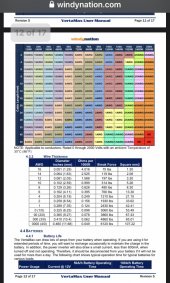
8 awg, 0.63 milliohms per foot, 150' round trip is 0.095 ohm.
0.095 ohm x 28A = 2.65V drop. Out of 82V, 3.2% loss during the broad peak current of the two-orientation array.

If you're running wire in conduit, here's 250' for $130


But if you pay for 6 awg, that gives expansion capability. or, get 500' roll of 8 awg and pull two sets.
Thanks Hedges, your helping solve this puzzle and it’s appreciated for sure.

I’m going to order another panel and try the 2s4p configuration.

These panels have 12AWG factory wire (6.5’).

You like 10AWG inter-panel wire with fuses and 8AWG for the 70’ run?
 
Thanks Hedges, your helping solve this puzzle and it’s appreciated for sure.

I’m going to order another panel and try the 2s4p configuration.

These panels have 12AWG factory wire (6.5’).

You like 10AWG inter-panel wire with fuses and 8AWG for the 70’ run?
And, can you comment on how exactly to wire these together?

Like would you include 2 sets of 4 to 1 branch connectors?

Then 1 set of 2 to 1 branch connectors?
 
4 panels in parallel is 39A, so have to be careful that any adapters can handle that. There might be an MC4 connector than can, but if it can't it'll burn up.

With 39A from PV, we're supposed to size wires and any fuses for 1.56x that (1.25 x 1.25), so 60A. That exceeds what 8 awg is good for in some thermal/cable environments. Individual 8 awg conductors in free air, 90 degree C insulation and 30 degree environment is OK.

If you run conduit, then 6 awg wire in that. At a junction box you could have four male & four female MC4 pigtails connecting to panel strings. Or two pigtails of each gender and use four 2 to 1 "Y" connectors (two of each gender.)

Best to stay around 20A per MC4 connector rather than hoping mix-n-match brands can carry 40+ amps.
If ultimately 4 strings are wired in parallel, get 4 MC4 fuse holders, and fuses the size named on PV panel label.
(Or a fused junction box with pigtails for all strings.)

I prefer more in series, fewer in parallel for higher voltage lower current. But SCC or inverter has to accept that. My hardware is good up to 600 Voc.
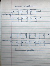
Are these wiring diagrams functional for 2s3p and 2s4p?
 

Attachments

  • A72B5CF8-3B5A-46C6-A383-655890F0ED37.jpeg
    A72B5CF8-3B5A-46C6-A383-655890F0ED37.jpeg
    104.1 KB · Views: 7
4 panels in parallel is 39A, so have to be careful that any adapters can handle that. There might be an MC4 connector than can, but if it can't it'll burn up.

With 39A from PV, we're supposed to size wires and any fuses for 1.56x that (1.25 x 1.25), so 60A. That exceeds what 8 awg is good for in some thermal/cable environments. Individual 8 awg conductors in free air, 90 degree C insulation and 30 degree environment is OK.

If you run conduit, then 6 awg wire in that. At a junction box you could have four male & four female MC4 pigtails connecting to panel strings. Or two pigtails of each gender and use four 2 to 1 "Y" connectors (two of each gender.)

Best to stay around 20A per MC4 connector rather than hoping mix-n-match brands can carry 40+ amps.
If ultimately 4 strings are wired in parallel, get 4 MC4 fuse holders, and fuses the size named on PV panel label.
(Or a fused junction box with pigtails for all strings.)

I prefer more in series, fewer in parallel for higher voltage lower current. But SCC or inverter has to accept that. My hardware is good up to 600 Voc.
Are these wiring diagrams functional for 2s3p and 2s4p?
(I think it might not, just checking to make sure though)
 
Are these wiring diagrams functional for 2s3p and 2s4p?

No.

Both show all panels wired in series, but because panels are in alternating orientation, most cancel out the voltage of each other. Like if you put two batteries in a flashlight, one backwards to make sure if the switch gets turned on it doesn't run the batteries down.

Orient all panels with - on left and + on right.
Connect the two wires on right together.
Then they will be 3s2p and 4s2p, with negative on left and positive on right.

If you want 2s, then remove the two right-most panels of the upper picture (after reorienting and rewiring as I've described) and it would be 2s2p.
Add another two panels connected to wire on left & wire on right, it will be 2s3p. Two more, and it will be 2s4p.
 
Here's a thread with pictures explaining series and parallel:

 
No.

Both show all panels wired in series, but because panels are in alternating orientation, most cancel out the voltage of each other. Like if you put two batteries in a flashlight, one backwards to make sure if the switch gets turned on it doesn't run the batteries down.

Orient all panels with - on left and + on right.
Connect the two wires on right together.
Then they will be 3s2p and 4s2p, with negative on left and positive on right.

If you want 2s, then remove the two right-most panels of the upper picture (after reorienting and rewiring as I've described) and it would be 2s2p.
Add another two panels connected to wire on left & wire on right, it will be 2s3p. Two more, and it will be 2s4p.
‘Both show all panels wired in series, but because panels are in alternating orientation, most cancel out the voltage of each other. Like if you put two batteries in a flashlight, one backwards to make sure if the switch gets turned on it doesn't run the batteries down.’

lol, ?

Back to the drawing board..
I’m going to study your reply.
Thanks for responding Hedges.
 
Here's a thread with pictures explaining series and parallel:

1618702262321.jpeg
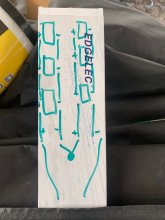
Is this a 2s3p configuration?
 
Is this a 2s3p configuration?

We call that "3p2s" because you did the parallel connection of 3 panels first, then connected those to sets in series.
To do that will require more "Y" connectors.

Try connecting a pair of panels in series. Do that 3 times. Then connect in parallel using "3Y" connectors. That would be 2s3p.
 
We call that "3p2s" because you did the parallel connection of 3 panels first, then connected those to sets in series.
To do that will require more "Y" connectors.

Try connecting a pair of panels in series. Do that 3 times. Then connect in parallel using "3Y" connectors. That would be 2s3p.
In the 3p2s connection, would the array produce ~30 amps and ~100 volts?

(VOC 50.4, ISC 9.74)


And, would the 3p2s be more shade tolerant than a 2s3p connection?
 
In the 3p2s connection, would the array produce ~30 amps and ~100 volts?

(VOC 50.4, ISC 9.74)

Yes.

And, would the 3p2s be more shade tolerant than a 2s3p connection?

I think so.
With 2s3p, if one panel is shaded, its string can't deliver current at the voltage of the other two. If other panel of a different string was also shaded, that string couldn't either and the array would produce 2s.
With 3p2s, in that shading case it would produce same as 2s2p.
 
Yes.


I think so.
With 2s3p, if one panel is shaded, its string can't deliver current at the voltage of the other two. If other panel of a different string was also shaded, that string couldn't either and the array would produce 2s.
With 3p2s, in that shading case it would produce same as 2s2p.
Would you suggest fuses for 3p2s array or not necessary?

(thanks for the info Hedges)
 
It is a bit of a toss up depending on the actual shade.


I would tend to skip the fuses. Fairly low power and for some fault to occur just right to cause trouble would be exceedingly rare.
When measuring the length of inter-panel wiring (for amperage rating), (4p2s context), should we measure the length from one panel y-branch connector to the next panel y-branch connector or the total length of the entire group of panels, (the total length of 4 panels in a row)?

Isc 9.74
 

Attachments

  • 1619039426025.jpeg
    1619039426025.jpeg
    264.8 KB · Views: 6
Last edited:
Length of wire doesn't matter for amperage rating. Amps heat a particular gauge of wire by some number of degrees.
Length matters for voltage drop. That may start to matter for 3 or 4 panels in parallel, but mostly I don't worry about it on PV side.
I care about voltage drop charge controller to battery, battery to inverter, AC wires inverter to load.

On a vehicle? Just size the PV wires to carry the current, without regard to length.
 
Back
Top