diy solar

diy solar

Array with variable number of panels.

elbac81

New Member
Joined
Mar 23, 2023
Messages
7
Location
Portugal
Hi everybody, first time poster, avid reader so far. Very much enjoying this forum :)

Here is my problem:
I have four solar panels, all of them have these specs: 590W max power, 53Voc, 44Vmp, 13 Amp max.
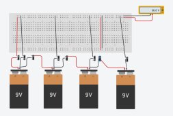
I want to be able to perform tests with 1,2,3 ou four panels in a serial array.
Some of the inverters I want to test need 1 panel, some may need more. You get the picture.

What I would love to do was to have an electric panel with all cables from the panels inserted, and "add" or "remove" each one from the bus via a switch/dc circuit breaker, etc...

I have limited electrical skills, so any help would be greatly apreciated

Thanks in advance!

Filipe

 
Last edited:
Since all that serial connection is is simply connecting the positive lead from one panel to the negative lead of the next there would be several ways you could set it up. From the simplest of plugging your output 2 wires with the MC4 connectors (don't do this under load) in after you connect the number of panels in series that you wish to test. To something elaborate with a series of switches that would add in the additional panels as you operate.

* Make sure you understand the need to size wire and connectors appropiate to the load they will carry.
 
To something elaborate with a series of switches that would add in the additional panels as you operate.

Thanks in advance for youreply, Mattb4

That would be the case, although I haven't still been able to figure out the sachematic for that.
As I wont be te only person operating this (this shall be a test array), the possibility to have a CB for each panel to add/remove the voltage would be perfect.

BTW, I am using 6mm2 solar cable, think it should be enough for a max of a little over 200V and 13Amps.

Thanks again.
 
Cleanest way is four breakers with only one ever closed at the same time. Between each panel you add a MC4 Y-connector, and run a + from the three Y's and the end panel, and the - from the first panel. It would not be fully code compliant in the US though, not sure about your local regs. Breakers would all need to be 250VDC rated.
 
If you wish to use breakers you would need 8. Each panels P and N wire comes into your switch box. Your first panel's wire has the positive connected to one breaker (call it A) and out to your load positive. The negative wire is split and connected to 2 breakers (one called B and the other S1). When the B breaker is on it goes to the output for the negative load side. When off, and the S1 breaker is turned on, it connects to the positive lead from your second panel. The second panels negative lead connects to 2 breakers (C and S2), S2 to the positive of the next panel, and C out to the negative side of load. And so on for all additional panel arrangements.

Test one panel: Breakers A and B are on and all other breakers off.
Test two panels: Breaker A and C on plus S1 other breakers off.
Test 3 panels: A and D on plus S1and S2.
Test 4 panels: A and E on plus S1,2,3.

Sounds good, I'm going to simulate it on tinkercad with batteries for panels, and if all is good than I shall proceed to the box.

Any sugestions on any other pnline electrical circuit simulators?
 
If you go with @Mattb4's suggestion you need to keep lead lengths short. The Y-connectors are better if you have long lead length. (I did omit the "-" single pole breaker in my reply above, this should be present.)
 
If you wish to use breakers you would need 8. Each panels P and N wire comes into your switch box. Your first panel's wire has the positive connected to one breaker (call it A) and out to your load positive. The negative wire is split and connected to 2 breakers (one called B and the other S1). When the B breaker is on it goes to the output for the negative load side. When off, and the S1 breaker is turned on, it connects to the positive lead from your second panel. The second panels negative lead connects to 2 breakers (C and S2), S2 to the positive of the next panel, and C out to the negative side of load. And so on for all additional panel arrangements.

Test one panel: Breakers A and B are on and all other breakers off.
Test two panels: Breaker A and C on plus S1 other breakers off.
Test 3 panels: A and D on plus S1and S2.
Test 4 panels: A and E on plus S1,2,3.
This solved it, brilliant! Thanks!


Tested it on tinkercad with 9v batteries, see attached pic.


Just one more question, if it's not too much to ask: Are there any risks involved in a bad setup of switches. I mean, of the switches are not turned on/off correctly, I allways get a reading of 9v 6amp or 0.
 

Attachments

  • Captura de ecrã 2023-04-11 152558.jpg
    Captura de ecrã 2023-04-11 152558.jpg
    90.5 KB · Views: 7
...


Just one more question, if it's not too much to ask: Are there any risks involved in a bad setup of switches. I mean, of the switches are not turned on/off correctly, ...
Causing my old mind to strain her. Unless I am missing something, having the neg output breakers (B,C,D, E) on along with the corresponding series breakers (S1,2,3) will just give you the next higher voltage without causing any problems with leaving them on. But on this I am not entirely sure. All other sequences would simply give you no output.
 
Well, just for random knowledge:

All switches UP = 9V (using 9v batteries)

"All other sequences would simply give you no output." - yes, other than the posted above (all UP) and the ones you mentioned above for 9,18,27,36V (using 9v batteries), there is no output. Thanks again my friend, you were very helpful!
 
Why not just run them into a combiner box? All the breakers are right there. No need to disconnect/connect MC4 connectors once they are all plugged in.
 
Combiner boxes are usually setup to parallel strings and not series connect them. The common ones only have one breaker for output but each string is fused. Often there is a lightning arrestor. I do see a few with breakers instead of fuses but they would have to be rewired quite a bit to achieve the switching capability that the OP was looking for.
 
yup, not enough coffee, didnt see the serial connections part. Carry on.
 
This solved it, brilliant! Thanks!


Tested it on tinkercad with 9v batteries, see attached pic.


Just one more question, if it's not too much to ask: Are there any risks involved in a bad setup of switches. I mean, of the switches are not turned on/off correctly, I allways get a reading of 9v 6amp or 0.
In your diagram there is no need for the disconnect between batteries; the only ones that actually do anything are the ones on the negative connecting to your upper bus. The lack of a disconnect between batteries just means that the potential of subsequent breakers is always what it would normally be.
 
Back
Top