diy solar

diy solar

ATS causing power surge inverter damage.

do you have a link
I have 3 Progressive 240v/50a. This one is 'plain' - https://www.amazon.com/Progressive-Dynamics-PD52V-Automatic-Transfer/dp/B003VAWNVK/ref=sr_1_1 and I have a couple of surge protection ones - https://www.amazon.com/gp/product/B0136U0QU4/ref=ppx_yo_dt_b_search_asin_title
The 'surge protection' that I assume is for large motor type situations such as a whole house AC compressor - you can get some surge if the sine-waves are not matched at switch-over... but I've never actually needed this :)

I have 3 of these Go-Power 30a 12v - https://www.amazon.com/Go-Power-TS-30-Automatic-Transfer/dp/B00153EYTO/ref=sr_1_2
 
thats the ats i think is causing the problem,and im not the only one,it was in wills video so i bought it
 
thats the ats i think is causing the problem,and im not the only one,it was in wills video so i bought it
The Progressive and Go-Powers are ETL/UL listed.

But I don't see how a 'surge' would go back to the inverter and it definitely should now 'rapidly' switch back/forth - which is why I asked how it's hooked up.
 
yeah i think ill switch the ats out,its only money lol,solar is expensive
The Progressive and Go-Powers are ETL/UL listed.

But I don't see how a 'surge' would go back to the inverter and it definitely should now 'rapidly' switch back/forth - which is why I asked how it's hooked up.
yeah dont have any rescent picks,three 12v gel batteries in parallel,inverter wire positive on the first battery neg.on the third battery,it works fine for days sometimes then boom kills the inverters smoked 3 1000w inverters but the 3000w inverter comes up with error opp,witch says its a ac short ,reset and good to go,wish i could point the finger at the ats but when im watching it its perfect,lights dont even flicker when it switches over,420w thats it
 
420w thats it
To my thinking 420w is excessive for a 1000w hf inverter especially considering the extra restart surges at switch over. Avoid the smaller ones and stay with the 3000w and the small constant load to keep it 'alive'. There isn't much difference in the self consumption of these inverters.
 
To my thinking 420w is excessive for a 1000w hf inverter especially considering the extra restart surges at switch over. Avoid the smaller ones and stay with the 3000w and the small constant load to keep it 'alive'. There isn't much difference in the self consumption of these inverters.
so happy ,thanks sunshine and all who chimed in,wow such a easy fix,night light .5 watts
 

Attachments

  • 20211211_190244.jpg
    20211211_190244.jpg
    122.2 KB · Views: 4
  • 20211211_190135.jpg
    20211211_190135.jpg
    68.5 KB · Views: 3
Background: So I just bought the MOES unit after reading all of the reviews on Amazon, looking here and elsewhere. I actually have a home brewed version on my small off-grid but (retired EE) but had set up for essentially zero DOD to preserve my one battery (Trojan) indefinitely. Had set to LV disconnect at 12.0 V under load which then recovers to ~12.7 V (fully charged). If interested find online Home Power mag #36 from 1993 (article entitled "Lead-Acid Battery State of Charge vs. Voltage). I went out the other day to try to change the LV disconnect but jiggled a wire (this was a breadboarded circuit) and "broke" my box. In that I like the LCD display, etc, of the MOES and I probably will be getting LiFePo within a year or so I was ok with shelling out the $100 for the MOES and in fact wish this was available when I put my system together 6-7 years ago!

So the last post here seemed to indicate that a night light load on the inverter was enough to "save the day"? My Xantrex does not go into a "sleep" mode but I did have a problem originally because the break/make on my relay was slow enough to trip the GFI on the inverter so I took it (the GFI from the inverter) out and put a stand-alone GFI after my "box". What isn't clear to me from the above discussion is what the root cause was to the smoked inverters. One item not disclosed was what were the actual values being used for the disconnect/reconnect voltages when the inverters were being smoked? Note that if too close just the natural recovery (see my comment above) could get the MOES to switch reasonably rapidly. I will be experimenting with the disconnect and my goal will be about 30-40% DOD on FLA until I replace with LiFePo battery(ies)...so between that and the lack of a sleep mode on my inverter I don't anticipate any problems.
 
to ~12.7 V (fully charged)
I don't anticipate any problems.
Unless the mfgr states differently I consider flooded batteries to only be “full” 12.8V+.
The cheap Walmartha batteries I use would occasionally hold 13.1 hours after dark last summer. 12.9 as interpreted by the inverter at or after sunset was most common, with an Ideal digital meter on the batteries reading 13.0

I’d want them to hold/have resting volts at a higher number. Others may have alternate opinions.
 
Hey 12VI-

I've been using 12.7 (more like 12.73) forever. Below is from Trojan website. BTW, I'm new to this forum and have not fully read the Rules/Regs so not sure if posting a URL is allowed but will find out now! https://www.trojanbattery.com/tech-support/battery-maintenance/ is where the pasted in table was found.

I have a decent digital VOM and measure at the battery with the battery switch (to inverter) in the off. Thus a true open circuit reading and at rest (30 or so minutes after any discharge).

I only found this forum after finding Will's u-tube videos. On solar panel talk . com, etc.

The main reason for my post was to see if the root cause for inverter fryings with the MOES switching unit had been discerned as I'm getting one next week. thx...

TABLE 1
State of Charge as Related to Specific Gravity and Open Circuit Voltage
Percentage of ChargeSpecific Gravity Corrected ToOpen-Circuit Voltage
6v8v12v24v36v48v
1001.2776.378.4912.7325.4638.2050.93
901.2586.318.4112.6225.2437.8550.47
801.2386.258.3312.5025.0037.4949.99
701.2176.198.2512.3724.7437.1249.49
601.1956.128.1612.2724.4836.7248.96
501.1726.028.0712.1024.2036.3148.41
401.1485.987.9711.8923.9235.8747.83
301.1245.917.8811.8123.6335.4447.26
201.0985.837.7711.6623.3234.9746.63
101.0735.757.6711.5123.0234.5246.03
 
Any transfer switch that switches between two non-syncronized AC sources needs to have time delay between connections.

Per their ad they claim inverter transfers to utility power ≤10ms, and utility power transfers to inverter ≤16ms. This is basically the time it takes for a mechanical relay to switch.

This is a recipe for blowing out equipment. Transferring from inverter to grid that have randomly different AC phasing outputs puts your equipment at risk. Transferring from grid to inverter puts inverter at risk with these small transfer times. Any AC motor will kick a high surge current when its AC source phase suddenly shifts. Many newer computer power supplies now have power factor correction circuitry that also does not like sudden AC input phase shifts.

For blowing out inverter, when an electric motor is running when ATS is on grid it is running with grid AC phase. When it quickly switches to inverter the running motor (compressor in refrig for example) will get hit with randomly different AC phase from inverter output resulting in a heavy surge currents kick back to inverter due to inverter being a random AC phase with respect to grid.

A UPS power supply pre-synchronizes its inverter, while in standby, so when called upon to backup, the inverter will run at same phase grid was before it dropped. When grid comes back on the inverter will slowly slew its phase to match grid before relay switches back over to grid. This ensures there is no abrupt discontinuity in AC source phase when switch overs occurs.
 
Last edited:
RC- appreciate your response. Note that I have a self-designed/ home-made version of this (battery input/comparator circuits/relays/etc) that is basically functionally identical to the MOES unit (without the nice LCD display nor the programable aspect). The only problem I ever had to solve was about 30-50% time of voltage "swap" my inverter gfi would trip and thus I found the work-around as per above. I put this together about 5 or 6 years ago (have a schematic somewhere but not sure if I dated it). I do not know the relay switching time but figure on the cusp (+/-) of what the GFI wanted to trip at. I have had no other issues. I do use AC motors (2 submersible (each 180 W or so) pumps for my pool...one to drive water through my pool solar panels to heat water and the other part of a water filtration system) but the one runs only when panels are hot (and thus sunny and thus high battery voltage) whereas the other has been subject to my switchover with no issues. Perhaps I've been ok as these are relatively low power motors and thus have had smooth sailing (small enough surges?)...and hopefully will have same-same with the MOES unit.

Also, per above (initial posting), I don't know why there was rapid cycling at sunset unless due to close LV/re-enable voltage settings? If not that perhaps the LV circuit isn't latching or doesn't hard switch quickly enough and thus becomes bi-stable? That would suck if so...but I still think maybe the guy had his two voltages too close together. Why I'm still not sure what the failure mode is based on that one observable.

Finally, I only have a 600 W inverter so that's the top end load I will subject the "50 Amp 5500 Watt" device with. Have a 6 amp circuit breaker to prevent overload which goes to the output of my device. Will be wiring that in line with the MOES unit. That circuit breaker has tripped only one time, and that's when someone plugged a (12 amp) vacuum cleaner into it!
 
Any update on the Moes/inverter issue?
i started this thread never really got a answer,a member suggested keeping the inverter active so i plugged a very low watt light in and i thought the problem was solved,but 2 weeks later it happened again,i was pulling 460 watts at that time,now i bought 2 new batteries and lowered the wattage to 230 watts no problems,but i will be going back up to the 460w range shortly.the inverters i blew were 1000w modified,the one im using right now is 3000w and instead of blowing ,it comes up with a error,reset and good to go,i have a 2000w pure sinewave inverter,scared to hook it up,but like i say nooooooooo problems at the moment,are you having problems
 
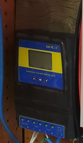
I suggest a careful read of RCinFLA's Jan 8 post on this thread. I agree with most of what he stipulated. That said, I installed my MOES unit a couple of weeks ago and am very pleased with its performance. I have a Xantrex 600 W PSW inverter and it has run flawlessly for about 5 years. My current nominal load when the MOES switches between sources is less than 100 W (I run other things like a crock pot, recharge tool batteries, etc...during days with full sun) and non-inductive (no motors). I will be utilizing (and have in the past with my previous home-brewed Mains/Inverter DPDT relay based switch...one that does everything the MOES does but not set up to be variable disconnect/reconnect voltages) a submersible pump running off of this system which will cut over with the MOES (as it did before with my home brew). I think I will be ok (still) as my pump is only about 140 W and thus any surge is most likely small compared to say something switching at 8000 W (or more) AC window unit (or similar) especially if the compressor was on. Also, when I plug the pump back in my max load will be around 200 W when AC switches. I'm retired so able to futz around to make these things (manual load adjustments!) happen.

As for a solution...it's not super clear what this person did (below is a review I found on Amazon) but I think he's using the MOES device to trigger a stand-alone relay (he uses the terms "contactors" and "electrical/mechanical interlock" and I don't know what those are). Also has a picture but it's not super clear to me what he's doing. If anyone has an idea what he's using and how wired that might be helpful. To me it might just be using another relay controlled by the MOES unit. Note that he also cautions against inductive loads.

As a final note...as a teen I messed around with a lot of electronics and seem to remember messing around with a device called a timed delay relay. I think the one I had had a piece of metal that was heated when power applied which caused the metal to move and then make a contact, closing the circuit. No coil in the relay. Seem to recall it taking several seconds. Not sure if a more elegant technology exists (probably a 555 circuit of some sort!) but certainly a break before make circuit could be implemented. Problem with this is PCs/DVRs and similar don't like this. Case in point, we get the occasional 1-5 minute outages here and my DVR receiver takes about 20 minutes to go through all of its churning to come back up! Maybe fix (though probably expensive if more than one needed) is a UPS on anything that doesn't like >1 or 2 second loss of power.


link to review here: https://www.amazon.com/gp/customer-...ef=cm_cr_dp_d_rvw_ttl?ie=UTF8&ASIN=B07F12RDZ2

Customer Review​


mr cheese

1.0 out of 5 stars S K E T C H Y ... could be great but its a hazard just waiting to fail
Reviewed in the United States on September 10, 2020
Verified Purchase
It does work but this thing is not safe. For one there is no mechanical interlock. That is a must for two relays or contactors supplying different sources of power! It has a good chance of frying your inverter. Not if but when. It is a fire hazard for sure. The logic / solid state part of this device is great the screen and menus and ease of use. But were the actual power relays come into play is beyond sketchy. If you put inductive loads on this device it becomes a very very sketchy device. Inductive loads are very hard on contacts and often cause contacts to weld together. If this happens you have a fire hazard with this device. Trust me. I have 2 electrical degrees. Also never believe any power ratings from china! This would never pass UL listing test standards. Never!

**Update**
I found a work around solution for my needs with 2 contactors and an electrical/mechanical interlock from ABB. I used "public power" to energize the contactors. I wired it in reverse essentially. I used 1 hot wire only to the output and it feeds out of the inverter or public power to their respective contactors. This is way way safer.
The problem is if you use this as intended and the relay associated with the public power fails it will back feed to your inverter and destroy it. If you dont believe me take it apart and see for yourself. The solid state electronics(which work great!) Energize two form C relays that their commons produce the "hot" wire and neutral output. Please do the same or risk a relay failure which 100% will destroy your inverter. Just read the other 1 star reviews where this has already happened.
 
After about 3 months, my original Giandel 2000/4000 watt Pure Sine Wave inverter stopped working with an "OL" light. The unit was seldom switched to grid power and the manufacturer suggested it might be a backfeed issue from the Moes unit. I tested it and found nothing that seemed out of line, but contacted Moes and asked if this was a possibility. Their response was: "It is unlikely that the device will feed back to the inverter and cause damage to the inverter. There is a safe interval distance between relay touches, and usually there is no back-feeding situation.
Inverter damage is usually due to the grid switch to the inverter when the inverter suddenly full load work, can not withstand the impact, so damaged."
Giandel, did replace my inverter, their customer service was outstanding. But for now I am going to run everything off the inverter and considering going to a manual transfer switch. I will be interested in seeing if SunnySoCal sees any feedback. I did read the customer review off the Amazon site that SSC posted and couldn't really figure out the work-a-round he was talking about. I also thought that maybe a device, with a diode, between the inverter and ATS might work to stop any back feeding issues. Let me know if anyone figures out what is causing this. I'm going to e-mail Giandel and see if the inverter going from "sleep mode" to full power might be an issue.
 
Just a question that popped up while reading this thread:
I am planning an emergency backup for some critical loads. I was actually thinking of keeping the 1500w pure sign wave inverter off, untill needed (to eliminate no load draw from the battery) . I will be using an ATS (not Moes) that will supposedly switch fast from grid to inverter. I was thinking of using a 12v relay connected to the grid using a small AC adapter, which will keep the inverter switch open when grid power is available. Then when grid goes down, the relay will go to normally closed and switch on the inverter. This will be in parallel to the ATS switching the loads to the inverter.
Is this a bad idea? could this burn my inverter (loads ON when inverter starts)?

The inverter is Xijia (CNSPOWER) like Andy (off grid garage) uses, but mine is 12v 1500w. It seems to have a "soft start" function, where the output AC voltage ramps up to 230v when it's first turned on.

Should I somehow get the inverter to fully power on before applying loads with the ATS? (don't know how I'm gonna do this, but asking if it's preferable).
Thanks...
 
My two bits on the last two posts. Those more learned than I please correct anything wrong I may state. First, I am a retired EE but mostly on the electronics/microwave RF side and did not take any power courses in my college days. I learned a boatload about house wiring leading up to when I had grid-tie installed.

First...if the ATS is causing the damage to inverters (and I believe very likely) I believe it's highly likely to be doing so upon switching from house power (grid) to the inverter. Reasoning is there are two independent relays within the MOES device (I think I saw a pic with the cover off and also I think someone, somewhere said that!) which switch the line and the neutral*. Thus, any transients (surges, mis-matched phasing of inductive loads, etc) switching from inverter to house power happens "upon" the house wiring which I think of as a monster surge absorber! Switching from grid to inverter all of those surges will juice the inverter causing the failures folks here (and Amazon reviews) have noted.

I liked the MOES unit (and my home brew) as its primary function is to protect the battery from over discharging. For me (now) this occurs sometime in the evening but at some point I want to go to a high enough Ah LFP battery so that nominally this circuit won't come into play. I agree with RCinFL that switching large or large and inductive loads without a time interval (maybe 1-3 seconds) as a break/delay/make is a bad idea. I will report back if my inverter dies but as I said before I used my home brew (one vs. two relays) for about 4 or 5 years now without incident...but typical load at reconnect ~150-200 Watts at most. In that I have that submersible pump on a timer I probably won't tempt fate and have it (for now, before getting the nirvana of a LFP battery!) stay off from sunup until I get sufficient battery voltage on the MOES to get the inverter switched on.

While this probably doesn't really help much as we would all like this thing to work just peachy going to both sources this post may give you the opportunity to run in a manner that doesn't smoke your inverter.

As an aside, I have only one battery now but had two when I put my system together and thus purchased a marine A/B battery switch. It rotates to 4 positions (Off/A/B/A+B) but there's a notation on the device that says "disable load before switching". I bring this up because the manual that shipped with my MOES also had a little color brochure that had a schematic on how to use this as a battery switching device (two batteries, one inverter). Instead of hooking up grid and inverter and output to your load they have battery1 and battery2 and then output to the inverter (and thus the loads). They caution to keep under 50 amps (this at 12 V nominal) which tells me the relays are or should be rated at that amperage and if memory serves me correctly that would be over some number (unspecified but likely 5000?) switches. My battery switch is break before make as it's a rotary type switch but also must have non-rated high current surge contacts. Not that any poster or reviewer was using the MOES in this way (per the brochure) but I'm curious if a rapid transition between two batteries at the inverter input would be problematic. I suspect not as there's most likely a reasonably large capacitor across the input terminals. Food for thought if anyone wants to repurpose this unit.


*I like this from a safety perspective because I don't think there would be smoke if only one relay failed and the likelihood of a relay failure probably much higher than the control electronics (but still a possibility). My home brewed unit was a single relay so probably less safe.
 
Reading this, I'm wondering if Vgrid->batt and Vbatt->grid are set too close for the battery bank size. Solution is either a bigger battery bank or to set those points further apart.
 
Back
Top