Since you are in UK, it is probably a safe assumption it is a 230V version of the inverter. I do not have experience or information on the 230V versions, so I can only assume it does dynamic bonding. To verify this, please check for continuity between Neutral and ground when the inverter is disconnected from everything. If you find continuity, it is nearly certain the unit does dynamic bonding.
For the rest of this post, I will assume the inverter does dynamic bonding.
This is my best guess of the model of the dynamic bonding in the MAX:
View attachment 132069
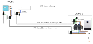
Plugging that into your situation in the simplest arrangement we get this:
View attachment 132070
When in passthrough mode the inverter is sharing a ground but is otherwise completely isolated from the inverter
When in battery mode the inverter is sharing the ground but the output neutral and hot wires are completely isolated from the grid.
If you want to put an isolating transfer switch in, the story does not change.
View attachment 132081
Sharing ground does NOT mean a ground fault will be "injected" into the grid. The ground fault current on the output of the inverter will remain on the dynamic bond of the inverter.