Well I saw a used 3000VA isolation trans on eBay today, and the price is right to get this project squared away. But it would be good to travel in this RV, and the weight of a proper US dual split inverter likely would be less than the Growatt 5000 plus true iso trans. Not to mention less monkeying around getting it right. I'm leaning towards selling it.


You are using an out of date browser. It may not display this or other websites correctly.
You should upgrade or use an alternative browser.
You should upgrade or use an alternative browser.
Auto transformer dangers
- Thread starter John Schmidt
- Start date
copec
Solar Enthusiast
- Joined
- Jan 23, 2021
- Messages
- 335
I would go with what he said If you explained it to him and he seemed to think it was okay. He has experience with a lot of setups with the inverters he sells.Should I just sell the Growatt and get one for US power? I spoke with Ian from Watts247 on the phone today because I had bought it from him. He didn't think I needed to sell it, but perhaps he didn't fully understand my setup.
Hedges
I See Electromagnetic Fields!
- Joined
- Mar 28, 2020
- Messages
- 20,604
To save weight, a split-phase or pair of stacked 120V high frequency inverters seems like the way to go.
The voltage converters you linked, I was looking for documentation of auto-transformer vs. isolation, but it didn't say. It did say 26 lbs.
Looking at Grainger, 3000VA transformers were 55 lbs whether auto or isolation. Of course, industrial units heavier than consumer.
Good to buy the best fit product for our application.
RCinFLA
Solar Wizard
- Joined
- Jun 21, 2020
- Messages
- 3,563
Couple of comments on this.Isolation transformer seems like a reasonable way to make do with these 220V or 240V inverters.
A full isolation transformer is larger, heavier, and more costly compared to same kVA auto-transformer. Benefit is you get full isolation.
I looked up Growatt auto-transformer spec. A box weighing 33 lbs. will not contain an auto-transformer capable of supporting a continuous 5 kVA L-N step down 120 vac 60 Hz load without getting very hot. True continuous load capability is in the range of 2-3 kVA, but this would be very confusing to average DIY user with a 5kVA 240vac inverter. They are playing the statistical game of expecting only balancing difference in current from 120 vac opposite phase loading.
I have two Thordarson 2kVA full isolation transformers, model 23V608. They each weigh 52.5 lbs with their 2 kVA isolation rating. I bought them about 20 years ago from Allied Electronics distributor for $265 each. I looked them up today and they are $959 each.
Nice thing about these 23V608 isolation transformers is they have two separate 120 vac primaries and two separate 120vac secondary windings so you can create a lot of different options.
You can wire an isolation transformer as an auto-transformer and get twice the VA capability of full isolation wiring. Just have to get the wiring phasing correct when you wire it for autotransformer.
Often, full isolation transformers have a slight turns ratio difference between primary and secondary to make up for transformer losses in output voltage under moderate load. This is minor and typical no more than 2% increase in no-load output voltage compared to input voltage.
Attachments
RCinFLA
Solar Wizard
- Joined
- Jun 21, 2020
- Messages
- 3,563
Would it be possible for you to draw out what you were describing in scenario #2?

Attachments
Last edited:
Hedges
I See Electromagnetic Fields!
- Joined
- Mar 28, 2020
- Messages
- 20,604
Nice thing about these 23V608 isolation transformers is they have two separate 120 vac primaries and two separate 120vac secondary windings so you can create a lot of different options.
You can wire an isolation transformer as an auto-transformer and get twice the VA capability of full isolation wiring. Just have to get the wiring phasing correct when you wire it for autotransformer.
I've been pondering that.
Certainly you have enough core for 2x the VA. Likely the windings can carry only enough current for half the VA rating of transformer to couple from one secondary winding to the other. Auto-transformer only has to convert half your power, so it can support a 120V load of 1x the VA rating of the transformer.
The way it works with an auto-transformer is that half the VA is coupled magnetically from one 120V winding to the other, and half the VA is current conducted through one 120V winding.
Make sure the neutral connection to the (two) 120V windings can carry 2x the current you're putting it each of L1, L2. It will be exactly the current your 120V load is drawing. One easy way to do this is with four wires, two for one 120V winding to L1, N and two for the other 120V winding to N, L2.
Often, full isolation transformers have a slight turns ratio difference between primary and secondary to make up for transformer losses in output voltage under moderate load. This is minor and typical no more than 2% increase in no-load output voltage compared to input voltage.
Which should work fine in the intended direction of conversion from primary to secondary.
The two 120V secondaries will be identical, which is as good as you can get for 240V isolated in, 120 series with 120 for 120/240V out.
If always stepping down from 240V to 120V, or always stepping up from 120V to 240V, you'll always have a bit of voltage sag. That's where you might prefer to start with +2% voltage no-load, sagging to -2% under full load. Instead, you'll get 0% sag no-load to -4% full load. Not a problem with an inverter delivering rock solid 120Vrms, so long as you don't also have excessively long skinny wires.
I haven't run into a situation of an inverter complaining about powering up a transformer yet, but about my only first-hand experience is 5000W Sunny Island feeding a 9kVA toroid as auto-transformer.
This issue is that a transformer with a winding intended for say 120V, has enough inductance to keep current extremely low (< 1% of rated current) for 1/2 cycle of AC without "saturating". Then polarity reverses, and it again blocks current flow.
When power is removed, leaving the core magnetized to some degree, next time power is reapplied it may magnetize core further in same direction, or demagnetize in opposite direction.
If it gets hit twice in the same direction (positive going cycle just before turn-off, another positive going cycle when turned back on), the core can saturate and cease acting like a big inductor. Instead, only winding resistance limits current to about 10x to 50x nominal.
I'm testing this at work right now. I got 70A peak current through a 12Arms transformer (that's only about 4x or 5x peak.)
One transformer manufacturer recommended using the outer layer winding as the driven one, rather than inner layer. That has more leakage inductance to the air, so saturation of core has less effect.
I would expect cheap undersized transformers to be more of a problem. Also cheap marginally designed inverters.
If you buy an isolation transformer with 2x 240V primary windings and 2x 120V secondary windings, and if each 240V winding can handle the current you want, you can make an auto-transformer that should never saturate.
Connect the two 240V windings in series, 240V + 240V = 240/480V split-phase. Now feed the outer L1 & L2 with your 240V inverter and have center tap as neutral (bonded to ground for an off-grid system; can't help you with autotransformer on a grid-tied system.)
Because you're using a 240V winding for 120V, it has 100% margin and should never be driven into saturation.
Brute force and big iron wins.
I don't expect anyone who isn't a magnetics guy to understand this. I'm just learning it. But avoiding the problem is necessary to prevent tripping of circuit breakers or causing inverter to shut down.

Saturation (magnetic) - Wikipedia
RCinFLA
Solar Wizard
- Joined
- Jun 21, 2020
- Messages
- 3,563
One of the surge issues with transformers is their core residual magnetic hysteresis. The core may have some residual magnetic bias from that last time it was turned off. When turn on voltage phase happens to be exactly opposite to the residual magnetic bias it can create higher initial surge current.
A lot of cheap transformers skimp on core size to save cost. The windings are adjusted to a lower turns per volt ratio to reduce the EMF drive on the skimpy core to avoid getting too close to core saturation. Having less turns per volt also saves on copper wire cost. This causes greater primary no-load magnetization current and more eddy current losses in core. They usually have a warmer core after sitting with no-load for a period of time.
The use of silicon-iron alloy laminates for low freq transformer core is to reduce eddy currents in core. Silicon-iron has a poorer electrical conductivity which, along with laminate layers, helps reduce eddy currents in core. One thing that has always bothered me is when I see a transformer core with a welded bead line across outside of the core laminates. It can't be good for reducing eddy core currents although laminate electrical isolation is likely not that good anyway.
John Schmidt
New Member
- Joined
- Dec 30, 2020
- Messages
- 82
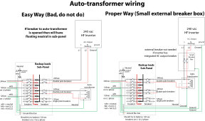
Awesome diagram! I've seen so many complex solutions, but this is "KISS". Very nice. One comment: If this was to feed the main panel rather than a sub panel, the ground and neutral would be bonded at that main panel. I don't see that as a problem (it is good, and required IMO), but I'd like your confirmation please! Again, excellent diagram!
timselectric
If I can do it, you can do it.
- Joined
- Feb 5, 2022
- Messages
- 18,531
Yes, it should have a N/G bond. The "sub panel " in the drawing doesn't show any other power source. So in my opinion, it should also have a N/G bond.Awesome diagram! I've seen so many complex solutions, but this is "KISS". Very nice. One comment: If this was to feed the main panel rather than a sub panel, the ground and neutral would be bonded at that main panel. I don't see that as a problem (it is good, and required IMO), but I'd like your confirmation please! Again, excellent diagram!
RCinFLA
Solar Wizard
- Joined
- Jun 21, 2020
- Messages
- 3,563
When voltage ratio is 2:1, no more core flux, EMF, or winding current. Maximum VA as auto-transformer = 2 * VA as isolation transformer, for same transformer.I've been pondering that.
Certainly you have enough core for 2x the VA. Likely the windings can carry only enough current for half the VA rating of transformer to couple from one secondary winding to the other. Auto-transformer only has to convert half your power, so it can support a 120V load of 1x the VA rating of the transformer.
Sounds like something for nothing and counter intuitive, but it is true.
Was easier for me to understand when the step up/down voltage is not 2:1. This link may help explain.
When step up/down voltage is small ratio, the VA multiplication is very high for auto-transformer. When step up/down voltage ratio is great, then VA auto-transformer approaches same as isolation transformer.
Manufacturers can play games with specs of auto-transformers' and statistics of use profiles.
Problem with autotransformers is protecting them from overload and allowing a higher powered inverter to supply greater current 240vac loads. Only way is to have a controllers that senses auto-transformer neutral current and/or auto-transformer core temperature measurement that trips the 240vac breaker from inverter via a solenoid actuator or remote control input to inverter to shut it down. Victron autotransformers have this controller and solenoid deactivated 240vac breaker. It is done properly.

Last edited:
RobertGreen
Solar Enthusiast
- Joined
- Mar 15, 2021
- Messages
- 308
I have noticed that as well, and it drove me nuts because I didn't understand if it was being done for a design or EM reason, or if it was just being done to physically attach the laminas (as opposed to an alternative like a bolt or clamp)One thing that has always bothered me is when I see a transformer core with a welded bead line across outside of the core laminates.
Hedges
I See Electromagnetic Fields!
- Joined
- Mar 28, 2020
- Messages
- 20,604
When voltage ratio is 2:1, no more core flux, EMF, or winding current. Maximum VA as auto-transformer = 2 * VA as isolation transformer, for same transformer.
I might have to double check, but I think if I use a typical 240V + 240V primary, 120V + 120V secondary as an auto-transformer, there will only be enough copper cross-section to make use of half the core's capability. That's doing 120+120 for the auto-transformer.
If all the copper had been dedicate to two identical windings, e.g. 120V primary 120V secondary, then I could put more VA through it without overheating the windings. That one would have a slight turns ratio difference, so better for a 120V to 120/240V split phase than for 240V to 120/240V split-phase.
Buying a transformer rated 2x the VA you need, and then only getting half the VA through it (limited by copper), you shouldn't have to worry about the transformer inrush issue. Because it could take a positive going half cycle, turn off, followed by another positive going half cycle, without saturation.
RCinFLA
Solar Wizard
- Joined
- Jun 21, 2020
- Messages
- 3,563
This is a whole different and more complicated discussion. You need to include a grid transfer switch or a lockout function, like sliding breaker toggle restriction plate modification to breaker panel to ensure main grid breaker and inverter input breaker are not allowed to be engaged at same time.One comment: If this was to feed the main panel rather than a sub panel, the ground and neutral would be bonded at that main panel. I don't see that as a problem (it is good, and required IMO), but I'd like your confirmation please! Again, excellent diagram!
I am not a fan of these lockout plate modifications for main panel. It is a poor man's jerry-rigged transfer switch. The price they typical ask for a couple small pieces of metal and a couple of screws is also hard for me to swallow.
You also have full house load breakers on inverter so have to manually manage engaged branch breakers so not to allow an overload on inverter.
Hedges
I See Electromagnetic Fields!
- Joined
- Mar 28, 2020
- Messages
- 20,604
I agree the breaker interlocks are overpriced ($50, about the price of an entire breaker panel with its busbars). Also, because most are mounted on the cover, it is defeated when cover removed.
The price is not bad for value/alternative. Any quality transfer switch of same rating would cost far more.
It is UL listed, and the breakers have been tested for proper isolation. That is worth a lot.
I now have several of them. Some are add-on interlocks, and one came pre-installed in a 100A panel with recessed plug for generator cord. That assembly cost something closer to $200. I think its mechanism remains operational when the bezel is removed.
I did get a cheap imported DIN rail 2-pole 63A transfer switch. But at well under full load I heard buzzing, and decided I didn't trust it.
Possibly the claimed amperage was a miss-statement. This one has -63 on the label, but also C25 and is claimed 25A.

There are legitimate brands with the same functionality (and able to gang multiple parts for additional functions.)
The price is not bad for value/alternative. Any quality transfer switch of same rating would cost far more.
It is UL listed, and the breakers have been tested for proper isolation. That is worth a lot.
I now have several of them. Some are add-on interlocks, and one came pre-installed in a 100A panel with recessed plug for generator cord. That assembly cost something closer to $200. I think its mechanism remains operational when the bezel is removed.
I did get a cheap imported DIN rail 2-pole 63A transfer switch. But at well under full load I heard buzzing, and decided I didn't trust it.
Possibly the claimed amperage was a miss-statement. This one has -63 on the label, but also C25 and is claimed 25A.
Circuit Breaker Dual Power Din Rail Manual Transfer Switch Rated Currents MCB | eBay
Mounting: 35mm din rail. Rated current: 25A.
www.ebay.com
There are legitimate brands with the same functionality (and able to gang multiple parts for additional functions.)
RCinFLA
Solar Wizard
- Joined
- Jun 21, 2020
- Messages
- 3,563
I watched a video today that showed the inside of one of the '5kVA' autotransformers with integrated over temp protection switch.
The concern is it appears the thermal switch is just in series with auto-transformer neutral connection. This would be very bad as it would save the autotransformer but put all your 120vac appliances risk with a floating neutral.
The concern is it appears the thermal switch is just in series with auto-transformer neutral connection. This would be very bad as it would save the autotransformer but put all your 120vac appliances risk with a floating neutral.
John Schmidt
New Member
- Joined
- Dec 30, 2020
- Messages
- 82
Yes. I've been thinking about the complexity that I have created. It is somewhat easy for me, but nothing that my wife could do, even if I wrote really good instructions. We are thinking of renting out the house during the winter, and I would never trust a renter to use the off-grid inverter. I need to clean things up. This has been an interesting project, and I've yet to flip the switch on anything. Maybe that is a good thing! Thank-you for your help.This is a whole different and more complicated discussion. You need to include a grid transfer switch or a lockout function, like sliding breaker toggle restriction plate modification to breaker panel to ensure main grid breaker and inverter input breaker are not allowed to be engaged at same time.
I am not a fan of these lockout plate modifications for main panel. It is a poor man's jerry-rigged transfer switch. The price they typical ask for a couple small pieces of metal and a couple of screws is also hard for me to swallow.
You also have full house load breakers on inverter so have to manually manage engaged branch breakers so not to allow an overload on inverter.
eddieriv95
New Member
- Joined
- May 2, 2022
- Messages
- 2
What I have
I have the Growatt 5000 US Inverter and the Solaredge Auto Transformer. It is fed by 3250W of PV and tied to a 15kwh LiPo battery bank. There is a PV combiner box for 2 strings tied in to a PV shutoff switch feeding the inverter. Roughly 180VDC at 15-18A input. This is an off grid application.
Please help clarify
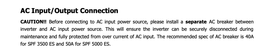
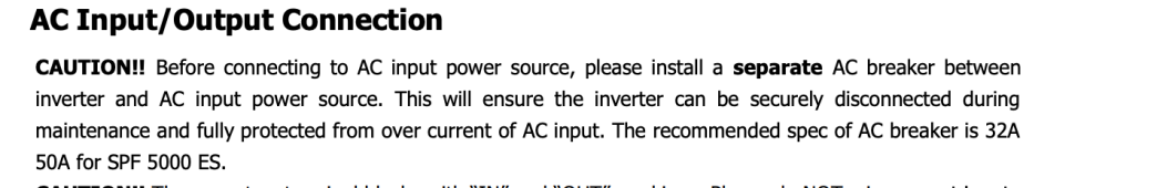
The manual states (version 1.0) and (version 4.0) either 32A and 50A or 40A and 50A respectfully within the following sentences from on page 10 (attached) while the Signature Solar wire diagram . I assume this means AC input from grid source requiring 32A (v 1.0) or 40A (v 4.0) and 50A (both manual versions) for AC Out from inverter. I assume AC Out terminates (L1 and L2) to 50A d-pole breaker. Clarification of this requirement is appreciated.
Ability to de-energize at source and prevent 240V pass through to 120V circuits on AT failure
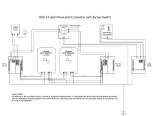
My proposal to de-energize AC output both at source (apart from on/off button on inverter) AND to provide a circuit fail safe (ensure that both the inverter and autotransformer are not in a condition where the AT trips or is turned off accidentally while the Inverter continues to provide 240V AC Out involves (1) a knife switch (say a Siemens 60A 240V general duty switch non-fusible) between the inverter and loads panel to ensure ability to quickly cut AC out power as/when needed and then to connect (L1/L2) on through to a 50A d-pole breaker in the loads panel. (2) The Auto-transformer neutral (N) is connected to the neutral bar of the loads panel while the AT L1/L2 is to be tied to a 25A d-pole breaker (signature solar diagram and solaredge AT manual) or 30A (as I've seen in other videos). My solution is to deploy a quadplex tandem breaker (50/30/30/50) for the Inverter and AT (for example Siemens Q23005CT2). I figure this will provide a measure of safety while ensuring both the Inverter and AT are either (1) both live or (2) both dead to prevent (3) Inverter live/AT dead condition.
My current loads are minimal 30A 120V RV trailer connection to be energized via single pole 30A breaker), 15A 120V single pole (shed lights), 15A single pole breaker (shed plugs), 15A (outside shed plug). These loads will be on the same panel as the Inverter and AT. Next year, I will add service to a small cabin (via a sub-panel) to include a mini-split 12000 BTU (@12-15A 240V), lights and plugs for two rooms (@4-15A circuits) and a water pump (not spec'd but I expect 15A-20A draw plus surge requirements @ 240V).
Will this work and is it a solution that makes sense for off gird application of this Growatt/Solaredge system? Am I out to lunch!? Any advice appreciated!
I have the Growatt 5000 US Inverter and the Solaredge Auto Transformer. It is fed by 3250W of PV and tied to a 15kwh LiPo battery bank. There is a PV combiner box for 2 strings tied in to a PV shutoff switch feeding the inverter. Roughly 180VDC at 15-18A input. This is an off grid application.
Please help clarify
The manual states (version 1.0) and (version 4.0) either 32A and 50A or 40A and 50A respectfully within the following sentences from on page 10 (attached) while the Signature Solar wire diagram . I assume this means AC input from grid source requiring 32A (v 1.0) or 40A (v 4.0) and 50A (both manual versions) for AC Out from inverter. I assume AC Out terminates (L1 and L2) to 50A d-pole breaker. Clarification of this requirement is appreciated.
Ability to de-energize at source and prevent 240V pass through to 120V circuits on AT failure
My proposal to de-energize AC output both at source (apart from on/off button on inverter) AND to provide a circuit fail safe (ensure that both the inverter and autotransformer are not in a condition where the AT trips or is turned off accidentally while the Inverter continues to provide 240V AC Out involves (1) a knife switch (say a Siemens 60A 240V general duty switch non-fusible) between the inverter and loads panel to ensure ability to quickly cut AC out power as/when needed and then to connect (L1/L2) on through to a 50A d-pole breaker in the loads panel. (2) The Auto-transformer neutral (N) is connected to the neutral bar of the loads panel while the AT L1/L2 is to be tied to a 25A d-pole breaker (signature solar diagram and solaredge AT manual) or 30A (as I've seen in other videos). My solution is to deploy a quadplex tandem breaker (50/30/30/50) for the Inverter and AT (for example Siemens Q23005CT2). I figure this will provide a measure of safety while ensuring both the Inverter and AT are either (1) both live or (2) both dead to prevent (3) Inverter live/AT dead condition.
My current loads are minimal 30A 120V RV trailer connection to be energized via single pole 30A breaker), 15A 120V single pole (shed lights), 15A single pole breaker (shed plugs), 15A (outside shed plug). These loads will be on the same panel as the Inverter and AT. Next year, I will add service to a small cabin (via a sub-panel) to include a mini-split 12000 BTU (@12-15A 240V), lights and plugs for two rooms (@4-15A circuits) and a water pump (not spec'd but I expect 15A-20A draw plus surge requirements @ 240V).
Will this work and is it a solution that makes sense for off gird application of this Growatt/Solaredge system? Am I out to lunch!? Any advice appreciated!
Attachments
timselectric
If I can do it, you can do it.
- Joined
- Feb 5, 2022
- Messages
- 18,531
Yes, it will work.Will this work and is it a solution that makes sense for off gird application of this Growatt/Solaredge system? Am I out to lunch!? Any advice appreciated!
Similar threads
- Replies
- 29
- Views
- 763
- Replies
- 20
- Views
- 1K
- Replies
- 56
- Views
- 2K
- Replies
- 14
- Views
- 760