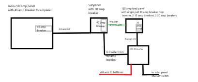
I see a problem with my design, it calls for a 60 amp breaker in a 40amp subpanel. Could you look at it and see if you agree. thanks
I don't see "40 amp subpanel" labeled.
I do see "40 amp breaker" feeding, so that would be the current limit.
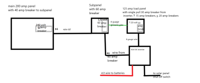
I don't understand the purpose of extra panel with 60A breaker, would just run wire from main panel. 60 A and 6 awg.
"4.0 wire" and "6.0 wire" aren't designations I recognize. "8 gauge" I do.
The wire to batteries will be at lower voltage therefore higher current than the AC wires.
For 40A, use 8 awg. For 60 A use 6 awg. For 30 A use 10 awg. (Or heavier gauge, which is a smaller number gauge)
Note the "**" next to 14, 12, 10 awg. That says to operate at reduced current, don't actually use the ampacity shown in chart.
Inverter data sheet suggests 30A breaker on output, 60A on input because it could be charging battery while also bypassing power to output.
It suggests10 awg, which would only be for the 30A output, need 6 awg for 60A input.
"125A load panel"
OK to use a panel rated for that much current, but inverter will only deliver 25A. Smaller panel OK if enough slots.
Inverter is 120V single phase. That could mean using only every other breaker position in panel, or wiring to feed both phases. But that is difficult while also including a 30A breaker in the panel. I could come up with ways to do it.
You won't find a panel with 30A main breaker. The wires from inverter to breaker panel will be hot, so it is undesirable to have them land on a branch circuit breaker which could pop out and have exposed hot contacts. There are kits which secure a branch circuit breaker with straps (e.g. generator backfeed kits.) Using one of those has the advantage that you can bypass inverter if it fails and feed the sub-panel from main panel instead.
2, 15A and 2, 20A breakers consume 4 slots (or 2 slots if tandem breakers used.)
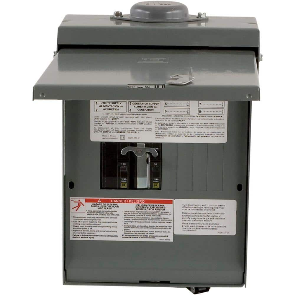
Here's a panel that I think would do everything you need. I use one. Expensive at $200 (a bit less elsewhere) but quality and all functions desired.
The Square D by Schneider Electric QO 30/100 Amp 4-Space 8-Circuit Temporary Transfer Generator Panel helps you change from utility power to a standby source with the flip of 2 QO main circuit breakers.
www.homedepot.com
I would feed one pole of the 100A breaker with 6 awg from 60A breaker in main panel. Neutral bar 6 awg from main panel. Ground with appropriate gauge (could be 6 awg or a smaller gauge, left as exercise for reader)
I would feed one pole the 30A breaker from output of inverter.
Because this is 120V only, not 120/240V, I would run 6 awg wire between the lugs of L1 and L2 busbar in panel.
Inverter input I would feed from same 60A run coming from main panel to this sub panel. Neutral and Ground use busbars in panel. The only trick is hot Line, because you aren't supposed to put two wires in the screw terminal of 100A breaker. So I would splice two wires together with a split-bolt.

Now, all 4 remaining slots in the panel are available for branch circuits, all connected to same 120V source.
Source can be either inverter output or grid (main panel), with interlock to safely select between them.
Output of inverter is protected at 30A.
Input of inverter is protected at 60A.
If inverter fails, just flip interlocked breakers to bypass.
Only catch is, when failed inverter is bypassed, the input wires to inverter are still hot. Have to turn off 60A breaker while unmounting inverter, and cap wire ends before turning breaker back on.
Here's mine.
The black lumps are split-bolt splices, wrapped in rubber tape and vinyl tape. (Inverter output can backfeed this panel and one other.)
I replaced 100A/30A breakers with 70A/70A. The lugs feed house, and two breakers select either grid or inverter as source.
The unused generator plug has its wires in ground bar. Have since replaced with an outlet fed by GFCI breaker.


")