diy solar

diy solar

AWG 8 10 mm2 cables

frankz66

New Member
Joined
Sep 6, 2022
Messages
575
Location
Aci Sant'Antonio Catania
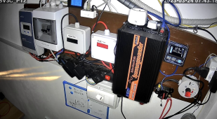
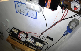
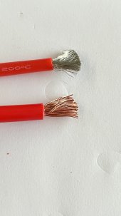
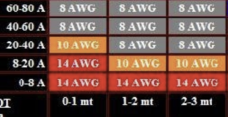
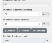
Hi everyone, I wanted to ask for a technical info about a pair of cables that I bought from 8 awg 10 mm2. These cables are made of soft material I believe silicone (see photo), composed of hundreds of very thin wires and as stated by the manufacturer, low impedance. I should replace some cables of a 300 ampere storage, which even if of almost 4 kw, the charge from the regulator that will end up in these batteries will never exceed 45 amps of maximum current (about 15 ampere per battery). The maximum distance from the battery to the inverter is about 80 cm, very short, the load that the reverse will support will be an average of 400 watts and rarely peaks of 1000 watts (very occasionally). The invert is a 1000 watt pure wave edecoa with a maximum power of 2000 watts. Making a calculation for the cables and the powers used to me, a cable avg 8, 10 mm2 in reference to the table is able to support up to 3 mt 80 ampere of current. That said, in the photo I present an 8 awg 10 mm2 cable with quite large and small copper wires and always in the photo the cable I bought from the same section but as written before with miles of wires (it also cost a lot 2.5 meters 32 euros). In your opinion this soft cable indeed very soft and with low impedance (I don't know its meaning) is better or even better indicated to replace the old one? The three 110 amp batteries are connected to each other with 10 mm2 cables. Thank you Ps: Being composed of hundreds of very thin wires, did I buy it wrong?
 

Attachments

  • 8 awg.jpg
    8 awg.jpg
    272.3 KB · Views: 13
  • Screenshot 2023-03-22 alle 18.11.53.png
    Screenshot 2023-03-22 alle 18.11.53.png
    573.2 KB · Views: 13
  • Screenshot 2023-03-22 alle 18.12.21.png
    Screenshot 2023-03-22 alle 18.12.21.png
    79 KB · Views: 13
Last edited:
That's silicon "superworm" wire. You can see the 200°C rating on the insulation. Super fine silver plated copper strands. It's as good as it gets for a given gauge. I have about 200' of the stuff. Love it.
Hello and thank you for answering. So can I replace it with the old one for battery ions and the transport of the current to the inverter? Also, before connecting it to the connector, should I solder it? Thank you Ps: The wires are very thin like hair wires !!
 
Hello and thank you for answering. So can I replace it with the old one for battery ions and the transport of the current to the inverter?

I don't know. What is the inverter voltage and power?

Also, before connecting it to the connector, should I solder it? Thank you Ps: The wires are very thin like hair wires !!

A quality crimp is fine.
 
1000W/12V/.85 = 98A

That wire has a 200°C insulation rating, so it can handle 83A according to:


If you limit the inverter to:

83A*12*.85 = 847W, you're good on ampacity.

Voltage drop is less than 3% @ 83A and 80cm:


so that's good too.
 
1000W/12V/.85 = 98A

That wire has a 200°C insulation rating, so it can handle 83A according to:


If you limit the inverter to:

83A*12*.85 = 847W, you're good on ampacity.

Voltage drop is less than 3% @ 83A and 80cm:


so that's good too.
Thank you for your very technical and comprehensive answers. I ask you, if I also put the old one in parallel with this cable to increase the current, does the voltage suffer or do I find myself a condition of having duplicated to 20 mm2?
 
Thank you for your very technical and comprehensive answers. I ask you, if I also put the old one in parallel with this cable to increase the current, does the voltage suffer or do I find myself a condition of having duplicated to 20 mm2?

If you note in the voltage drop calculator I linked, there is an option to include additional wires of the same size:

1679595887816.png

Both (+) wires would need a suitable fuse.
 
If you note in the voltage drop calculator I linked, there is an option to include additional wires of the same size:

View attachment 140989

Both (+) wires would need a suitable fuse.
Thank you, you give me some information that is increasing my knowledge more and more! So, by putting 2 cables in parallel for each pole from the graph the voltage drop is minor. Yesterday I connected the old cables together with the new ones, just to see if I could have more performance. I wanted to ask you if possible, a technical info. In the 1000 watt pure wave edecoa inverter I ran tests. Making a summary , the batteries are 3 , AGM 12v 110 amps c100 . My perplexity due to my knowledge raised a doubt about the performance. Last night I had a load of only 50 watts (the usual ...) , I bought a coffee machine that the manufacturer declares at the level of consumption 450 watts, so an absorption that can be considered modest compared to other machines in the industry. I wanted to try, so at monitor with the epever software I ran the test. The batteries had a voltage of 12.35-12.40 . As soon as the coffee machine was turned on, the absorption was slightly seen from the home light, my watt-detecting instrument immediately reported an instant consumption of about 520 watts. I managed to make coffee ....... But what I wanted to ask you is if the voltage drop from 12.35 to 11.59 during this phase is a normal value or did I have to expect less fall ?? Thank you
In addition, I increased or rather replaced the fuse at the output of the batteries with a larger one a 150 amp, those that can be restored with a lever. I update the post at 11.00 AM. I tried what was written with the panels in operation so during the day and the drop in power was derisory or it held up very well clearly with the panels in operation with 520 watts in production ..
 

Attachments

  • 21.png
    21.png
    3.1 MB · Views: 6
  • 23.png
    23.png
    2.2 MB · Views: 6
Last edited:
520W/12V = 43A

43A/200Ah (C20 rate) = 0.2C, which is 4X the 0.05C rating, so this is a high current and will produce a notable drop.

12.35 to 11.60 drop seems too much.

The next time you make coffee measure the following with a handheld voltmeter:

Voltage at battery terminals.
Voltage at inverter terminals.
Voltage across the breaker in the circuit.
1679674267931.png
 
Ciao
520W/12V = 43A

43A/200Ah (C20 rate) = 0.2C, which is 4X the 0.05C rating, so this is a high current and will produce a notable drop.

12.35 to 11.60 drop seems too much.

The next time you make coffee measure the following with a handheld voltmeter:

Voltage at battery terminals.
Voltage at inverter terminals.
Voltage across the breaker in the circuit
520W/12V = 43A

43A/200Ah (C20 rate) = 0.2C, which is 4X the 0.05C rating, so this is a high current and will produce a notable drop.

12.35 to 11.60 drop seems too much.

The next time you make coffee measure the following with a handheld voltmeter:

Voltage at battery terminals.
Voltage at inverter terminals.
Voltage across the breaker in the circuit.
View attachment 141116
Hi, and thanks for the directions. I immediately made the measurements with a digital tester at the points you indicated but at the moment with a constant load of just 120 watts. The tester reads 12.83-84 respectively in the points with the red arrow and at the exit of the regulator ! I wanted to add that last night when I did this test, the batteries marked the voltage reported above, but they had already given energy for TV and more, in short, a few hours of production that made it go down a little. Instead, I believe that this drop depends on the type of battery and quality ... They are AGM deep cycle batteries for almost 180 euros, probably by my feeling they are not excellent quality batteries such as trojans or renogy or other. However, I update you even more, today I performed tests with the panels in production, charging about 370 watts continuous net of the consumption of the inverter I think 10% more then 400 watts, in addition to all this load I made sure to power a tool from another 250 watts to arrive in real time to about 650 watts! I noticed that the batteries were going down a little e.g. 13.volts at 12.50 and the panels dispensed 540 watts . Finally from the photos I showed you at the exit to the fuse I connected another positive in parallel and another negative in parallel from 8 awg . Today I had asked the battery manufacturer how many amps I could ask to dispense to the batteries without stress explaining that I had 3 in parallel from 110 amps and he replied that I could ask for 30 amps ..... For me this did not understand a ...... !!However, the batteries are new, even if I made the mistake as a beginner to buy one at the end of Agiosto 2022 and the other two one in January 2023 and the other in February 2023 .....

In addition, I attach you right now at sunset and a load of 110 watts net of inverter consumption after today's tests ...
 

Attachments

  • st.png
    st.png
    463 KB · Views: 2
Last edited:
520W/12V = 43A

43A/200Ah (C20 rate) = 0.2C, which is 4X the 0.05C rating, so this is a high current and will produce a notable drop.

12.35 to 11.60 drop seems too much.

The next time you make coffee measure the following with a handheld voltmeter:

Voltage at battery terminals.
Voltage at inverter terminals.
Voltage across the breaker in the circuit.
View attachment 141116
Another update ... Now that in cut out, with a load of 110 watts I have turned on the coffee machine bringing the consumption to over 600 watts instantaneous. The voltage from 12.60 dropped for a few seconds to a minimum of 11.91 so about 0.69 volts. This time I carried out the test with the cables in parallel that I inserted from the fuse to the inverter increasing the 8 awg to 16 awg total .
 
Another update ... Now that in cut out, with a load of 110 watts I have turned on the coffee machine bringing the consumption to over 600 watts instantaneous. The voltage from 12.60 dropped for a few seconds to a minimum of 11.91 so about 0.69 volts. This time I carried out the test with the cables in parallel that I inserted from the fuse to the inverter increasing the 8 awg to 16 awg total .

What were the three values during the coffee run?

Voltage at battery terminals.
Voltage at inverter terminals.
Voltage across the breaker in the circuit.
 
Back
Top