diy solar

diy solar

Back Flow Current - Blocking Diode

sshibly

Solar Enthusiast
Joined
Dec 8, 2020
Messages
531
Blocking diodes.

1. Meanwell and other power sources, boost converters - good practice to use a blocking diode to prevent current back flow.
2. Solar panels have the same to prevent batteries from being drained when the sun don't shine :)

This thread is to collect the Off the Shelf products out there we can use and post your solution for blocking diodes.

Previous Threads:


Possible Solutions:

Question:
1. Will this item work ? DIODE MODULE 600V 60A SOT227B , this a Fast Recovery Epitaxial Diode (FRED), sounds fancy, but comes in a mountable solution.


2. Aliexpress has 15A and 50A blocking diodes already mounted on panels,


curious why they skipped the heat sink on these.
 
Blocking diodes are unnecessary, and a complete waste of time and money. That is of course unless, you're using panels and a charge controller from the 1970s...
 
If you're using a power supply as a charger thats a definite yes!

Having cooked 8 meanwell RSP-300-3.3s because I didnt have diodes I'd say you absolutely need diodes - if you're going to leave them hooked up when discharging. And you will because sooner or later you'll forget to disconnect the festering things. If you search you'll see a few discussions I've been in about the subject.

You'll need to parallel a couple/few shotty diodes depending on your amperage, because of the way shottys work they self level well. You can't use axial diodes because you'll need to attach heatsinks. Look for the diodes that have a flat metal tab as part of the diode, you'll need to attach your heat sink (with heatsink grease) to that since its got a large surface area to transfer heat. Shottkey diodes have the lowest forward voltage drop.

Actual charge controllers dont need diodes, they have them already built in.
 
  • Like
Reactions: Dzl
I guess what I should have said was. Diodes are unnecessary and a complete waste of time and money. If you are using the proper equipment. If you are trying to rig something up to do a job it was never meant to do, of course you are going to have to make some modifications to it. I personally would use a power supply with CC-CV or a charger with current limiting on it, that was made to charge batteries. But that's just me. I understand where you're coming from.
 
Question:
1. Will this item work ? DIODE MODULE 600V 60A SOT227B , this a Fast Recovery Epitaxial Diode (FRED), sounds fancy, but comes in a mountable solution.

No, it's a silicon diode and is going to generate a ton of heat and has a really nasty voltage drop.
2. Aliexpress has 15A and 50A blocking diodes already mounted on panels,


curious why they skipped the heat sink on these.
This would work, and for what it is it's a pretty basic but slick implementation of an ideal diode - which isnt actually a diode at all it just acts like one, which is why it doesnt need a heatsink because there's no actual forward voltage drop to generate heat. There'll be a little bit of loss in the mosfet that'll generate heat but not much, I'd stick a small heatsink on it anyway.
 
If you're using a power supply as a charger thats a definite yes!

Having cooked 8 meanwell RSP-300-3.3s because I didnt have diodes I'd say you absolutely need diodes - if you're going to leave them hooked up when discharging. And you will because sooner or later you'll forget to disconnect the festering things. If you search you'll see a few discussions I've been in about the subject.
What killed the meanwells?
Synchronous rectification on secondary side or what?
 
This would work, and for what it is it's a pretty basic but slick implementation of an ideal diode - which isnt actually a diode at all it just acts like one, which is why it doesnt need a heatsink because there's no actual forward voltage drop to generate heat. There'll be a little bit of loss in the mosfet that'll generate heat but not much, I'd stick a small heatsink on it anyway.

I wonder what is the minimum current that the above "ideal" diode still operates reliably?
Looks like manufacturer has grind off the controller markings so that it would be harder to judge their incompetence. :unsure:

Edit: found other pictures of similar shunt and the diode controller is Linear product(or clone..)
Looks like LT4357 or 4359 would be good candidate for the actual chip: https://www.analog.com/media/en/technical-documentation/data-sheets/4357fd.pdf
So it actually maintains the gate voltage at such a level that the mosfet has constant 30mV drop and it is easy to sense which way the current is flowing even at low current. I wrongly assumed that these would turn on the mosfet totally ON making the sensing at low currents difficult.
 
Last edited:
  • Like
Reactions: Cal
What killed the meanwells?
Synchronous rectification on secondary side or what?
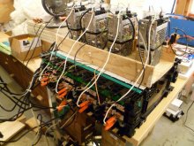
I rigged up a 8 cell charger using the power supplies to parallel charge each cell in a BYD module to the exact same voltage because I was having a heck of a time getting a level top balance to do a discharge test. I was spending dozens of man-hours per module putting a PS on the lagging cells or burning off charge on the runners and I had 19 modules to test.

They got cooked in 30 seconds when on one module I'd turned the PSs off but forgot to remove them from the module and started the discharge, Poof! The discharging batteries back-flowed into the meanwells and cooked the output mosfets. 200 bucks of power supplies gone.
The photo is of version2, with diodes and mickey-mouse heatsinks.
P1030993.JPG
 
I wonder what is the minimum current that the above "ideal" diode still operates reliably?
Looks like manufacturer has grind off the controller markings so that it would be harder to judge their incompetence. :unsure:

Edit: found other pictures of similar shunt and the diode controller is Linear product(or clone..)
Looks like LT4357 or 4359 would be good candidate for the actual chip: https://www.analog.com/media/en/technical-documentation/data-sheets/4357fd.pdf
So it actually maintains the gate voltage at such a level that the mosfet has constant 30mV drop and it is easy to sense which way the current is flowing even at low current. I wrongly assumed that these would turn on the mosfet totally ON making the sensing at low currents difficult.
Looks like it wouldnt work for single cells though, not enough voltage to drive it.
 
If you are charging batteries with buck converters, that practically ALL have a reverse feed, omitting the blocking diode is an invitation to the magic blue smoke...
If you inadvertently make a short on the input side, while having the battery connected you can buy a new buck...
 
Buck-Boost converters - do these have reverse protection? can someone tell me how to check pls? some of these have on/off switch.

Boost converters - Supposedly the NEWER DROK boost converters have reverse protection, again, from what I have read/seen on youtube. I do not own a DROK boost or a clone, to $$$ right now for my ramen budget.

Buck converter - Definitely my elcheapo does not have one.

Meanwell - After reading Maast and other use of Meanwell, I went a little meanwell nutz. Reverse protection needed from what I read here, but here are my questions:
q1 - If the meanwell PS like RSP or HRPG series are capable of "CURRENT SHARING" aka parallel connection, why do we need backfeed protection? would the parallel PS not action like a battery and try to feed volts/amps up the another PS?

q2 - Diode based reverse current protection is inefficient and the suggestion was to use P-Channel MOSFETs, Though I understand the working, I have no patience or skills to fab tiny components and make one. Any clue if there are premade p-fets boards for reverse current protection?
 
Normally all MOS-FETs used in buck converters have a bypass diode built in, that will cause the backflow. It's in the very nature of buck converters.
You need an ideal diode module (these are what you call the premade FET balls for reverse current protection)
-between the battery and your buck converter (that will also prevent the quiescent current lost in your buck, which can be considerable on the long time) or
-between the panels and your buck converter ( if you need e.g. the built in display or Bluetooth to keep working).
 
Buck-Boost converters - do these have reverse protection? can someone tell me how to check pls? some of these have on/off switch.

Boost converters - Supposedly the NEWER DROK boost converters have reverse protection, again, from what I have read/seen on youtube. I do not own a DROK boost or a clone, to $$$ right now for my ramen budget.

Buck converter - Definitely my elcheapo does not have one.

Meanwell - After reading Maast and other use of Meanwell, I went a little meanwell nutz. Reverse protection needed from what I read here, but here are my questions:
q1 - If the meanwell PS like RSP or HRPG series are capable of "CURRENT SHARING" aka parallel connection, why do we need backfeed protection? would the parallel PS not action like a battery and try to feed volts/amps up the another PS?

q2 - Diode based reverse current protection is inefficient and the suggestion was to use P-Channel MOSFETs, Though I understand the working, I have no patience or skills to fab tiny components and make one. Any clue if there are premade p-fets boards for reverse current protection?
Q1: Current sharing only means they coordinate their output amperages via adjusting their output voltages, it doesnt do any type of protection from backfeed.
Q2: What you're talking about is called an 'ideal diode' and is completely doable, but unless you can find a premade one at the voltages you need I wouldnt recommend doing it yourself if you're a novice, it'll be a huge PITA for you to implement. I'm not a novice and I still wouldnt do one since a diode is so much simpler.
Shottkey diodes only have a forward voltage drop of .3 to .5v depending on how much current and they self-level. It does generate heat but its not especially inefficient - you'll only lose a few watts to it. As long as you have a plan to deal with the heat it's a dead-simple implementation and one I recommend.

Q1 - gotcha, synching output current, but if one meanwell puts out more volts than another in parallel then won't it act like a battery trying to backfeed? [sorry I think I am over thinking this]

Q2. Schottkey - makes sense, will this component work?

Schottky Diodes & Rectifiers 100 Amp 100 Volt 6300 Amp IFSM


Fabrication:
1. 2 inch x 4 inch heat sink
2. attach one end to the heat sink with thermal conductive compound > solder power cabel on top of this end
3. Solder wire to other end to load

buck converter > one end of STKY diode on heat shink > wire out > battery

with a 100A 100v diode how many STKY diodes should I put in parallel?
Good find on the diode

It depends on how much current you're going to be passing through it. In general I like to only use 25% of a diode capacity because it minimizes the forward voltage drop. The diode you found will work up to 100 amps but at that point its dropping .8v and would be generating a ton of heat.

Speaking of heat I'd put a fan on the heatsink too, be aware that the tab is electrically connected to one of the legs making it part of the circuit so it'll need to be electrically isolated. Make sure you use some heatsink grease too.
 
I will get a dozen of those diodes and mount them on a heat sink.

How do I go about testing if my buck converter does NOT have backfeed protection?
 
How do I go about testing if my buck converter does NOT have backfeed protection?
Unless you have a circuit diagram, or can trace the powerflows back along the traces and find a diode the only way to know is if you try to backfeed and you let the smoke out.
 
I will get a dozen of those diodes and mount them on a heat sink.

How do I go about testing if my buck converter does NOT have backfeed protection?
Easy: but the output on a battery an measure the input. If you read 0V it has a backflow protection, if you read ~ the battery voltage, it has not.
The magic smoke only comes out, if you make a short at the input (which is more likely to happen than you may think).
 
Back
Top