diy solar

diy solar

Backup down under

Love to know how and why my settings changed, especially since 230V is the default setting...
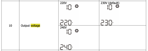
According to my manual there is an output voltage setting, #10 in the menu options:

Screen Shot 2023-04-13 at 8.18.47 pm.png

I just checked and that option appears in my inverter's set up menu. I didn't make the change as the house is currently running from the inverter (and I don't know what the consequence of making the change would be while it is operating) but I'll have a look at that tomorrow.

I'm pretty sure I looked at this before but resigned myself to it being a 230 V output. If I can change it to 240 V, I will.

It may need for the inverter to be offline or not inverting at the time, not sure.
 
I'm pretty sure I looked at this before but resigned myself to it being a 230 V output. If I can change it to 240 V, I will.

It may need for the inverter to be offline or not inverting at the time, not sure.
I tried and failed - the output voltage setting wouldn't stick.

Then I consulted a guru on these things and they said the inverter had to be off with at least one power source connected be it AC input or battery so the control panel would still be active and settings changed. So I did that and changed the output voltage setting to 240 V and it seems to have stuck. I'll know for sure later in the day when the unit cuts back to SBU mode.
 
System just cut over to SBU, a bit earlier than normal today as clouds came over this afternoon and battery was full.

In any case, the system is now generating 240 V AC output instead of 230 V AC. I think the reduced voltage jump on transition between grid power and inverter power will be a good thing.
 
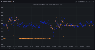
And a voltage chart to show the new operating voltage in action.

Orange dots are voltage samples of output from the off-grid inverter.
Blue are voltage samples for the AC input supply.
Chart for last 48 hours.

Screen Shot 2023-04-15 at 6.00.01 am.png

Can see the transitions between SBU and Utility First modes. Can also see how the inverter's new output voltage setting (240 V) has taken hold and is more in line with my grid's supply, making the transitions much less of a voltage jump.
 
System just cut over to SBU, a bit earlier than normal today as clouds came over this afternoon and battery was full.

In any case, the system is now generating 240 V AC output instead of 230 V AC. I think the reduced voltage jump on transition between grid power and inverter power will be a good thing.

That's what I figured, same as when you are setting it up for parallel operation, will change it over next time I have power off, really wonder how it changed though, I understand the cut on going back to default but voltage change away from default.
 
And a voltage chart to show the new operating voltage in action.

Orange dots are voltage samples of output from the off-grid inverter.
Blue are voltage samples for the AC input supply.
Chart for last 48 hours.

View attachment 144723

Can see the transitions between SBU and Utility First modes. Can also see how the inverter's new output voltage setting (240 V) has taken hold and is more in line with my grid's supply, making the transitions much less of a voltage jump.
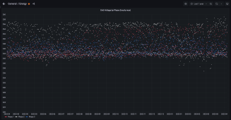
Wow, you really do stay around 240V.

Melbourne grid seems to mostly stay around 230V.
Screenshot_20230415_180007.png
 
Solar rails are so expensive, can barely even find used ones for some reason and those I can find cost the same or more than new!
Where did you get yours from?
 
Solar rails are so expensive, can barely even find used ones for some reason and those I can find cost the same or more than new!
Where did you get yours from?
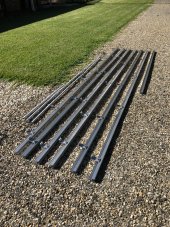
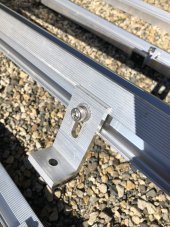
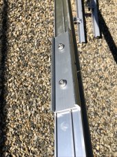
I kept an eye on FB buy/swap/sell sites as often people have old systems they are selling. In the end though I just called the installer of my grid-tied PV system and asked if they had any. They are regularly removing old PV systems when people upgrade, so often have old rails in the warehouse. They probably keep some for spares but in general it goes to recycling. So I made an offer to take some off their hands. Didn't quite have all the clamps I needed but it wasn't hard to order those.
 
This was what I ended up with for ~A$100 I think. About 25 m of rail. They even delivered it for me. I was due to have my grid-PV system given a check so arranged for them to do that and they delivered these at the same time.

30353E82-1143-469F-A17B-AC5EFC1AB645_1_105_c.jpeg

7123131D-F878-4708-927C-1DB0871220A2_1_105_c.jpeg

8309B791-0747-4D31-87CB-5E7C186D4018_1_105_c.jpeg

I didn't use it all, still have some spare. I will want to put up more PV in future so hanging onto it but I'd need more. Not sure if I'll do it myself though like last time, I might just get someone in instead.
 
We had a 10+ hour grid outage on Saturday and another couple of hours on Sunday. We were not home but the system kept power on without issue.

Some local decided to cut down a tree and brought down main district power lines in the process. :rolleyes:
 
OK, today's the day I plan to pull the whole battery out for a rebuild. I'm not actually looking forward to this as it's going to be very physically demanding and I am struggling at present.

When done I will have removed the old non-functioning inverter, installed the new DC busbars for the batteries and added an extra 5 kWh server rack battery to the two existing units, plus of course replaced the lead acid bank.

All up it's about 3/4s of a tonne of battery to move in and out of a tight space, plus all the fittings to be done. I'm just going to do one more final check that I have all I need before pulling this lot out.
 
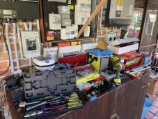
Some snaps from today.

Does anyone else have a mess like this when working?

F31306D5-2511-4274-889C-125581168DEC_1_105_c.jpeg

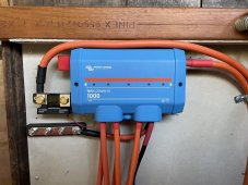
The Victron Lynx Power in, with added fuses. I direct connected the smart shunt to it. The Power in needs ~5 mm of packing behind it so it and the Smart Shunt can sit flush.

1F788415-B8C7-47E1-98FA-3A8992C01742_1_105_c.jpeg

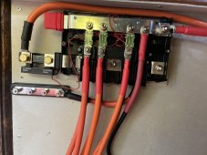
The extra busbar is for my lead acid batteries. They are separately fused with HRC fuses in a pull breaker.

Pop the cover on and it's all neat and tidy. No idea why the extra busbar looks wonky. It's fitted in line, optical illusion perhaps.

9DA38A94-69DA-4D12-B57D-B696E7773336_1_105_c.jpeg

It was dark by the time I finished so wasn't able to get a decent pic of the batteries. I'll get better pics tomorrow when there is light.

9E71E072-8F30-4E69-9DE8-BCEBC45A1713_1_105_c.jpeg

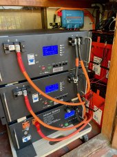
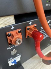
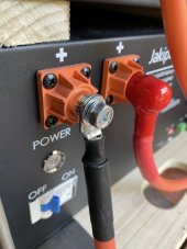
The new Jakiper is at the bottom, and the lead acid bank is to the right. I made that call as I was unable to remove one of the terminal bolts from the other batteries, so it's at the top in case I need to pull it off to sort that out. The bolt head and the screw are stripped. The bolts are pretty crummy quality. The bolts on the Jakiper are much nicer. I really like those terminals.

So that's 15 kWh of LiFePO4 with 20 kWh of sealed lead acid (Enersys SBF190F). I've been running a hybrid set up since August and it does great. The lead is for backup/outage reserve, while the LiFePO4 looks after the daily cycling.

When I turned them on the other batteries were back feeding the Jakiper and handful of amps, so they'll take a bit of time to rebalance. At least I got it all connected and we are running from battery tonight as usual.
 
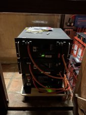
OK, daylight image of battery:

IMG_0112.jpeg

Can see the sealed lead acid as well, 20 kWh of Enersys SBS190F in two banks of four. I staggered the stacking of those so the terminal covers on the lower bank can be removed for checking terminals. Also provides a nice shelf for the two HA02 balancers.

No rack for me. I just put some timber spacers between the server rack units. I then read in the Jakiper manual that their battery is designed to be stacked on top of each other, up to three batteries in a stack. Debating whether to remove the spacers or not. Part of me thinks it will allow for cooling, not that they will get all that hot, while another part of me says it's just another spot for insects to crawl into.

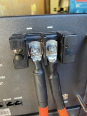
You can see the hanging terminal cable on the left negative terminal of the upper battery. That's the nut I was unable to remove. Both rounded and the screw is stripped. Nothing wrong with the socket and screw driver, these things are just crap hardware.

IMG_0113.jpeg

Because it is recessed inside the terminal I'm trying to work out the best way to safely remove it.
 
I picked up a bolt extraction kit today, those special sockets designed to bite into the bolt head. Hopefully it does the trick. Also picked up some new bolts to trial replacing these with. They really are pretty crummy bolts.

After the new combined battery had reached full charge (56.4 V) for a while I took some readings of the cell voltages to see how the originals are going and the new unit.

Code:
    Battery 1   Battery 2   Battery 3 (JP)
FCC    103.3      100.1      104.8
CC       226        232          1
Cell     mV         mV         mV
1      3,524      3,516      3,513
2      3,517      3,523      3,504
3      3,521      3,514      3,527
4      3,524      3,518      3,582
5      3,528      3,535      3,508
6      3,505      3,527      3,612
7      3,522      3,520      3,525
8      3,519      3,528      3,459
9      3,501      3,529      3,476
10     3,522      3,518      3,524
11     3,524      3,520      3,522
12     3,523      3,528      3,608
13     3,533      3,524      3,499
14     3,538      3,516      3,527
15     3,526      3,502      3,497
16     3,526      3,532      3,528
----------------------------------
MIN    3,501      3,502      3,459
MAX    3,538      3,535      3,612
DELTA     37         33        153
AVG    3,522      3,522      3,526
SD         9          8         41 

FCC = Fully Charged Capacity rating Ah as shown by the BMS
CC = Cycle count

Can see the new battery (#3) has quite an imbalance in cell voltages. I'll be interested to see if that settles down over time. Meanwhile the other two batteries are quite acceptable with 37 mV and 33 mV difference between their respective minimum and maximum cell voltages.
 
I picked up a bolt extraction kit today, those special sockets designed to bite into the bolt head. Hopefully it does the trick. Also picked up some new bolts to trial replacing these with. They really are pretty crummy bolts.
Used the tool this morning and the bolt came out very easily. Picked up some stainless steel M6 bolts, washers and lock washers and they fit just fine. Those bolts in the batteries must be made of some pretty soft steel.
 
I much prefer the terminals of the Jakiper over the other batteries I have. The Jakiper uses an M8 bolt, much nicer and secure to torque down.

14ED7685-5125-49EE-B117-CBBF74668DE3_1_105_c.jpeg 45810990-3837-4F7F-80A4-69C838A50BAA_1_105_c.jpeg
 
Another month ends so I look at performance so far...

As far as outage coverage goes, the system works exactly as it should. Last outage was for 10 hours when I wasn't home and it didn't blink.

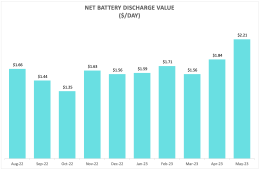
But since I have upgraded to enable it to do more, this is the financial benefit assessment of the battery:

Screen Shot 2023-06-01 at 5.48.58 am.png

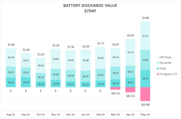
It's made up of offsetting grid power consumption during different time of use tariff periods, less foregone feed-in credit:

Screen Shot 2023-06-01 at 5.48.42 am.png
The foregone feed-in credit is a result of using my grid-tied PV to provide some supplemental charging as the small off-grid PV array doesn't generate enough energy at this time of year as we head to the shortest days of the year. It's worth it though as feed in credit is a fraction of the import tariffs.

Quite the jump in value recently as energy tariffs have risen substantially.
 
Another month ends so I look at performance so far...

As far as outage coverage goes, the system works exactly as it should. Last outage was for 10 hours when I wasn't home and it didn't blink.

But since I have upgraded to enable it to do more, this is the financial benefit assessment of the battery:

View attachment 151314

It's made up of offsetting grid power consumption during different time of use tariff periods, less foregone feed-in credit:

View attachment 151315
The foregone feed-in credit is a result of using my grid-tied PV to provide some supplemental charging as the small off-grid PV array doesn't generate enough energy at this time of year as we head to the shortest days of the year. It's worth it though as feed in credit is a fraction of the import tariffs.

Quite the jump in value recently as energy tariffs have risen substantially.
Have you played around with the solar forecasting in Home Assistant?
 
Have you played around with the solar forecasting in Home Assistant?
I was an early user of Solcast forecasting when the API was released a few years ago. I integrated Solcast into my HA dashboard not long after I started using Home Assistant and have solar PV forecasts for both my grid and off-grid arrays. Because I was an early Solcast account holder I get 50 API calls/day. New free Solcast accounts are limited to 10, but frankly that's still sufficient if used wisely.

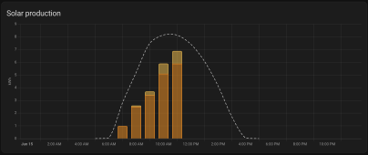
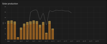
Can see the forecasts (dashed line) in the Energy Dashboard:

Screen Shot 2023-06-15 at 12.05.12 pm.png
Screen Shot 2023-06-15 at 12.05.29 pm.png

The actual production numbers show the grid PV and off-grid PV output. Grid system is 11 kW, off-grid 2.2 kW.

Unfortunately the forecasts are unable to account for my shading issues which do hurt production, particularly at this time of year and so they consistently overestimate what my system can generate by quite a margin.

Well to be fair, they could account for it if I had a paid subscription - Solcast have a way to constantly review your system's actual performance and tune the forecast settings to account for such things.

I use the Solcast PV forecast data in an automation which decides if/when my off-grid battery could use supplemental charge support from my grid PV. The automation monitors the forecast for my off-grid PV array as well as battery SOC / and energy required to get to 100% SOC. If the off-grid PV won't have enough generation to complete a charge, then it will set a sensor identifying supplemental charging from my grid PV is required.

Screen Shot 2023-06-15 at 12.09.12 pm.png

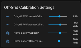
To account for the impact of shading on the forecasts I have calibration helpers set up so I can apply adjustments, both a factor and a fixed offset option. Those are set up as sliders I can adjust in the UI when I feel the need:

Screen Shot 2023-06-15 at 12.03.23 pm.png

It's working pretty well.

Idea is to maximise off-grid PV generation since that is "use it or lose it" generation capacity and so use only as much grid-PV energy as is necessary to get the battery charged while extracting all that the off-grid PV array has to offer.

Off-grid PV energy is "free", while using grid PV energy costs me 13c/kWh as that's what it would earn had it been exported to the grid instead.

The off-grid system needs supplemental charging support at this time of year, but in Summer half of the year it won't need much help from the grid-PV aside from poor production days.

I do want to add more off-grid PV at some point.
 
Back
Top