diy solar

diy solar

Backup down under

Finished off the conduit run today. Some pics this time:

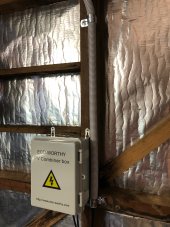
Combiner box inside garage:
IMG_2993.jpeg

It's a "value" choice box. It all seems in order and the cables are secure.
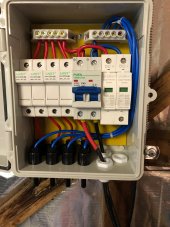
IMG_2992.jpeg

DC conduit run exiting garage:
IMG_2994.jpeg

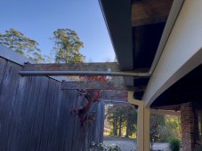
and then all along the facia board to other end of house:
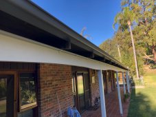
IMG_2995.jpeg

Conduit will be getting painted to match the facia. But I think I've made a rookie error - I just realised I haven't allowed for expansion joints... The far end exits into some flexi conduit, perhaps that will be enough but I'll have to see how it fares come Summer heat. If I notice some conduit bending I'll retro fit some expansion joints.

And near the inverter housing I have a DC isolator switch which is on the wall under the 2m wide eave:
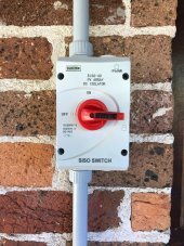
IMG_2996.jpeg

And from there the conduit extends to the inverter inside its housing.

While it's already connected to the inverter, I want to redo the terminal connections but not today. I have to disconnect and move the battery bank to do that and it's a bit of an awkward job. With other work I needed to do, this was enough.

I have my extra solar panel rail clamps now so the the last 2 panels can go up when I'm ready. I think I'll put the rails up but leave fitting those 2 panels until last as I need to work out my cable management for the 4 panels which are already in situ. Still waiting for my PV cable extensions to arrive, which are due to arrive in next couple of days.

Once I have those then I can finish off this job, switch on the panels and fingers crossed I haven't screwed anything up. I'll do a few multimeter checks on voltage polarity just to be sure.
 
MY PV cables arrived so it was time to started wiring these puppies in.

Didn't grab any photos today. Might get some tomorrow to post.

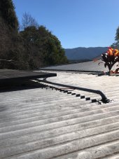
I drilled the roof penetration hole and affixed the dektite, pushed through a conduit elbow and got all the cables pulled through the conduit flex inside the garage and down to the combiner box, and then ran them through straight conduit along the garage roof with exit holes in the conduit for wires to connect to each pair of panels along the array.

After that it was connecting the first two panels in series, adding the MC4 connectors to the extension cable ends and connecting the first two panels. Then back at the combiner box I needed to work out which two of the three pairs of wires were from the connected panels. Simple multimeter voltage check told me which two were the right ones and so plugged them into position #1 in the combiner box.

Time to test if the inverter would recognise the panels were online and whether there would be any charge current flowing.

Before doing that I did a polarity check just to be sure. All good.

Turn off the grid power supply to the AIO inverter, turn off the inverter and then flip the solar DC isolator switch to on. Re power up the inverter and fingers crossed nothing starts smoking. All good, inverter starts up and after a while it recognised the solar panels were connected and a small current began flowing into the batteries. It was late afternoon by then, the panels were shaded and the batteries were already at float level charge so I wasn't expecting much in the way of production. But there was voltage (~70 something volts) and about 35W was flowing into the batteries, so about 0.5A.

It took most of the day and I'm pretty knackered. So much up and down the ladder and up and down to/from the roof. As an amputee with a prosthetic leg it takes longer to do most things and I need to take extra care. But I sure have an extra appreciation for professional solar installers who do this stuff day in day out. Obviously my efficiency is very low as every step of the way is my first time doing it. but I'm getting there.

Still plenty to do.

I have to connect the other two panels already on the roof. Then make up two more rails for the final two panels to be fitted and installed and connect those as well.
 
Great work. I saw current flowing into my battery for the first time only a couple of days ago, it's a good feeling. I have only installed half of my planned 12 panels on the roof so far and am with you on low efficiency. The pro's certainly get the job done quickly, but I think we amateurs can have an edge on quality, since we can be careful and take our time with things.
 
I tested the system operation today by hooking up the pool pump to see if the solar PV would run the pump. It does. :)
Did a little video of it:


Part way through the video I noted the solar PV voltage was 51V with a PV output of 420W while the display said only 1A, and I thought that wasn't right. Since then I realised the 1A reading was just for current flowing into the battery, not total current from the solar PV. The balance of course was being used to supply the output loads.

The two panels only (Pmax rating of 740W) were supplying ~420W and I saw 422W at one point. The panels are flat (2 degree slope away from the sun) and this is Winter sun at about 11:30am. At that time the sun's altitude was 40.7 degrees and so the angle of solar incidence would be 90+2-40.7 = 51.3 degrees. Cosine(51.3 deg) = 0.625 or I should expect about 62.5% of output.

62.5% * (2 * 370W) = 462W. So I was getting 422W/462W = 91.3% of theoretical panel output under STC conditions. Considering the cable losses, panel temps would probably be above STC, and I didn't quite have a full load running I reckon that's excellent.

I did also test it briefly with the pump running on its start up cycle, which draws about 920W. The MPPT was still supplying about the same power output so I don't think there was a load constraint.

That's was just 2 of 6 panels supplying power, so pretty confident the full array will be more than able to keep my pump happily running off grid. Test will be cloudy/rainy days to see how it goes.

Decided not to do any more work on the array today, although I may connect the other two panels later this afternoon if I feel up for it. Still a bit sore from yesterday's efforts and I had a cycling session at the local velodrome this morning as well.

IMG_3011.jpeg

Took a quick pic by reaching up to show the conduit and roof penetration/dektite. This will also be covered over when the final two panels go up.
 
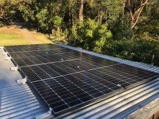
Finished off installing the PV array today, 2.22kWp:

IMG_3032.jpeg

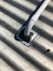
Better pic of the roof penetration/dektite, which is now hidden underneath the panels:

IMG_3021.jpeg

And all connected up and supplying power:

IMG_3016.jpeg

By the time I'd finished it was late afternoon so again low sun and some shading, plus the battery is just getting a float charge while the pool pump ran from the off-grid system all day.

Pretty happy with how its all turned out for my first ever DIY solar/battery project. Bit buggered now!

I still have a few small things to do. I want to redo the terminal connections into the AIO inverter (fit some ferrules), and I think I could use a better quality battery DC isolator and fuse arrangement than the one I have so need to look into that. And paint the conduit run to match the facia board.

This system will be capable of supplying quite a bit of energy I can't really use. Aside from the pool pump I don't have much of a load to give it. One future idea is a dehumidifier which can run in a yet to be constructed walk-in-robe which will be on the other side of the exterior wall from where the battery/inverter and circuit board are located. So an off-grid power outlet could easily be added for that.
 
How long is the pvc conduit on the roof? A big problem with using pvc on a roof is expansion and contraction. The stuff moves a LOT. Keep an eye on it. It may need to be changed to metal conduit. Or have expansion joints installed to prevent clamps tearing out, or fittings breaking.
 
How long is the pvc conduit on the roof?
The conduit on the roof is ~ 4m long. It is open ended at the far end and held up off the roof by metal cable ties on the rails so it can move relative to the rails and the cables all have some slack at their exit point from the conduit. It is shaded by the panels so hopefully that'll help.

The long straight run along the facia board is 20 something metres and I'm more concerned about that one.

A big problem with using pvc on a roof is expansion and contraction. The stuff moves a LOT. Keep an eye on it.
Yeah, I commented earlier that I probably should have put in expansion joints in the long facia board conduit run. I'll keep an eye on it and the rooftop conduit as well. Being Winter I'll be looking for bowing of the conduit as we head towards Summer. If it does then I'll retrofit one or two expansion joints.

We can and have had 40+C days here.
 
I have a question about grounding for surge protection.

The solar PV combiner box provides a connection for surge protection. The garage already has a copper earth rod which was fitted for the electronic radio dog fence and I could run an earth wire to that without much problem.

That earth rod however is not the main home earth, which is about 25m away, and uses an outside copper water pipe (in Australia water pipes used to be the typical earth point but nowadays the standard for new builds quite sensibly requires a separate earth rod).

Given it's just for surge protection of the array I figure using the garage earth rod is fine and there's no need to use the home's earth point. Thoughts?
 
Any plans for an automatic cutoff switch?

These are common here for backup generator installs. No interaction needed and the switch happens quickly.
 
Any plans for an automatic cutoff switch?
Not at this stage. I'll leave it as a manual transfer switch. Aside from being a "fun" project, it was also done on a budget and getting a 4 pole 3-phase auto transfer switch installed would be pretty expensive I'd imagine. Like nearly doubling the cost of the whole project.
 
Today was a good test of the off-grid system performance on a poor day. Overcast all day. As an indicator, my grid tied system output was 25% of previous days. And it's Winter.

After a day's pool pump cycle, charging a power tool battery (Ryobi One+ 2.5Ah 18V battery) and running the pool cleaning robot all from the off grid system my battery finished up the day at 90% state of charge. That's about 900Wh. All up the demand would have been ~2100Wh on the AC side so I guess on the DC side about 2500Wh. So the solar supplied ~1600Wh of the required energy.

Given the poor insolation conditions I'm pretty happy with that. I wouldn't normally run the other stuff on a poor day - I just wanted to try it and see. Tomorrow is forecast rain. Will just let it do its thing.

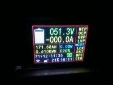
Battery state at end of day:

IMG_3043.jpeg
 
Great job, should be a good money saver for you - one step closer to off-grid :)
 
Yesterday was a rainy day keeping production down but the draw on the battery wasn't high and some sun later in the day had everything topped up by day's end. Today was cool and sunny and the battery was barely touched throughout the pump's duty cycle.

I might do an experiment by adding a heavy load to see how much power the array can pump out. I have an old 2 bar resistive element heater with settings for 800W, 1600W and 2400W. That should be enough to test the array's production. It's still Winter here with a flat array so the most I can expect is ~63% of Wp of 2.22kW = 1.4kW, less any other system losses.
 
Performed my little experiment today.

At ~10:45am I added some load to the system to see how much extra could be drawn from the 2.2kW of panels. I used an old resistive element heater. Managed to get PV output up to 1.05kW. Not bad for a clear Winter morning.

Video of the test (may be a little while before the HD version is processed.):


Now for the "theoretical" calculations:
Peak output noted: 1.05kW
2.22kW array
10:45 am
Sun altitude 39.75 degrees
Array tilt -2 degrees
Expected insolation at STC = cosine(90+2-39.75 degrees) * 2.22kW = 1.36kW
Panel temp unknown but guesstimate ~20C above STC
Temp coefficient -0.37%/C so temp losses ~7.5% = 0.1kW
Expected output 1.26kW
Actual output 83% of theoretical peak

Not sure what sort of losses the cable run create but hopefully not awful. I'll need to do some voltage checks at each end. It would be 35-40m cable run from panels to inverter, mostly 6mm² copper solar cable and via combiner box and DC isolator. Panels are in a 2S3P arrangement.

Happy with that.
 
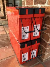
Got these today:

IMG_3064.jpeg

Another 9.1kWh (nominal) to double my existing battery bank.

Now I need to start planning how I'm configuring this addition - physically and electrically. Don't think I need too much - couple of cables. I already have connecting bus bars and an extra fuse for it but I'm not happy with my DC breaker and want to sort out a better solution for that. An extra balancer as well (I have one on the existing bank).

But I need to work out the physical set up.

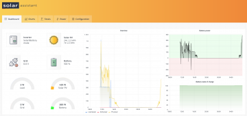
I also added the Solar Assistant real time monitoring and data logging system with the Raspberry Pi connected to the inverter. Works a treat. I'll share a video on that later.
 
Solar Assistant dashboard snapshot. Shows current live data (updates pretty quickly) plus a few charts showing past 24 hours:

Screen Shot 2021-08-21 at 7.40.39 am.png

Here's a video showing it in operation. It's a bit over 15-min long.


It was a pretty easy install. I went with the pre-configured device but you can supply your own Raspberry Pi and download the software - that would probably be somewhat cheaper. I've never used an RPi before so decided it'd just be easier to get it pre-configured.

I also note it provides some other nice summary screens about the inverter's set up:

Screen Shot 2021-08-21 at 7.34.48 am.png
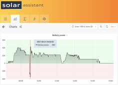
And the battery monitor page I don't think I showed that in the video:

Screen Shot 2021-08-21 at 7.36.42 am.png
 
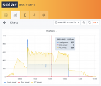
First full day with system monitoring. The first chart shows the pattern of the day which will be repeated quite a lot from now on.

Solar PV starts up slowly in the morning and the inverter gives the batteries a bit of boost charge after lying mostly idle overnight (pretty much just idle inverter consumption). Then as the batteries replenish the little bit of charge lost overnight the inverter drops PV output back down to float level current.

At 9am the pool pump begins its start up cycle, ~900W for 5-min. The inverter ramps up solar PV production while the battery supplies the balance of the load. After 5-min the pumps drops back to it's normal duty cycle and draws ~300W. PV output falls back down accordingly to cover the pump and supply a float charge. A bit overcast today but ample energy from the PV array to cover all that.

Battery state of charge never deviates from 100%.

Screen Shot 2021-08-21 at 8.12.05 pm.png

Screen Shot 2021-08-21 at 8.21.28 pm.png
 
Lovely sunny morning here so I decided to do two things.

One was to reprogram the pool pump controller to start 15-min earlier and end 15-min later. Based on yesterday's data it is clear (to me at least) I have enough solar PV capacity to extend the duty cycle. It's been on a shorter Winter duty cycle for a while and the days are getting longer and warmer, so the pump duty cycle should as well. I will be extending it more as Summer approaches. I actually bought an astronomical timer switch quite some time ago but never ended up using it. This auto adjusts start and end times based on day of year and the length of day. Another little project to revive.

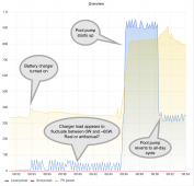
The other was an experiment. I figured I may as well give those batteries I got the other day a top up charge so I'm using one of those "smart" car battery chargers I use to keep starter batteries at the ready. Plugged it into the off-grid system this morning and hooked up one battery to the charger. This is the resulting load chart:

Screen Shot 2021-08-22 at 9.02.20 am.png

It was interesting to see the load chart fluctuating in that manner. I'm not sure if the charger is actually pulsing or the data is just some form of artifactual aliasing.
 
Another experiment today. This time to check using my backup generator as the AC input source for the inverter (rather than the actual grid).

This is to test the scenario when there is a long outage (>>12 hours) and some extra energy supplemental to that from the solar PV array is required to top up the batteries.

My inverter is a Yamaha EF3000ISE. It has a continuous output rating of 2800W and is an inverter generator. Electric start.

Plugged it into the 20A socket I have fitted for the inverter's AC input (which is normally plugged into a 20A switched grid outlet). Fired up the generator and switched the inverter over from SBU mode to Utility first mode.

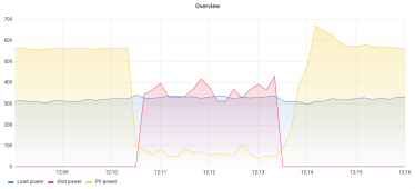
Unit seamlessly switched to passing through the generator's AC supply to the output without batting an eyelid. No issues on the output side, pool pump carried on without issue. The solar PV output was immediately reduced to only supply charge current to the batteries.

Here's some charts showing how this looked (horizontal axis is time of day in hh:mm):

Screen Shot 2021-08-27 at 12.26.40 pm.png

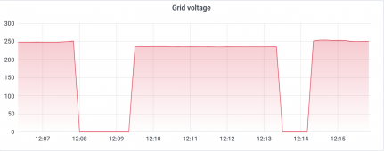
Looking at a few other charts, this is the "grid" voltage. I experience high local grid voltages, which are the two sections at either side of this plot. Grid before the change over to generator was at 248-252V, and after I switched back was at 250-254V. The generator supply (the middle section) was 235-236V. Grid standard AC single phase voltage here is meant to be 230V, with a tolerance of +10% to -6% (216-253V).
Screen Shot 2021-08-27 at 12.28.58 pm.png

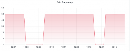
Grid frequency chart. No issues with this, which is to be expected from a quality inverter generator.
Screen Shot 2021-08-27 at 12.29.26 pm.png
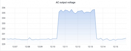
Lastly, the inverter's AC output voltage.

Screen Shot 2021-08-27 at 12.29.50 pm.png

230V is the inverter's output when power is supplied via solar PV/battery. When switched to Utility first mode to pass generator power through the inverter to the output, we can see the output voltage match the "grid" voltage of the inverter in the earlier chart and is in the 235-236V range. During few minutes of this test I also switched the generator in and out of its power saving mode, a mode where it adjusts engine speed to match the loads rather than run at full speed in order to save fuel. It made no difference to the supply although at 350-400W this is a fairly light load for the inverter (<15% of generator's continuous output capacity).

It was good to do a proper test to make sure I can have the generator supply power to the system. For all intents and purposes this ensures all but indefinite outage coverage.
 
Meanwhile the project to double the storage capacity is underway. I have on order I think all the remaining parts I'll need, being cable (2B&S / 35mm²), lugs (M6 & M8 to suit different terminals), hydraulic crimper, heat shrink, fuses, fuse holders, terminal busbars, and an extra battery equaliser.

I do however want to make a better back board to mount everything on, and am considering lining the entire box with cement sheeting for better protection.
 
Back
Top