wattmatters
Solar Wizard
An update. While the clone PIP4048HS inverter has been terrific and shown I can make an off-grid system work with great functionality and complement our grid-tied PV system, I've decided it's now time to upgrade to something a little more powerful.
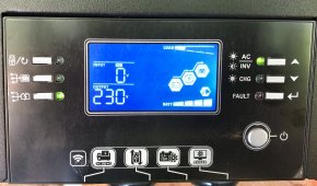
Since adding the server rack LiFePO4 batteries I've been running the house from this little PIP unit for a couple of months and it's been great. Before that it's been in operation for well over a year doing duty running the pool pump and keeping our backup reserve of lead acid batteries ready for outage backup. It's kept us going through numerous outages.
Since running the house with it we would occasionally experience overloads in the evening, and while the little PIP clone handles that well by instantly switching over to Utility pass through mode, I'd rather it didn't need to do that. I really don't want to be paranoid about every time the wife wants to make some hot tea while she has the microwave going for something else. Plus we have a second occupied dwelling as well which might be doing something similar.
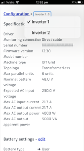
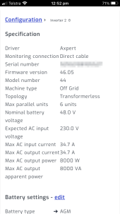
So I have picked up an EASun 8kW SMA MAX unit. The is the same unit as the MPP Solar PIP 8048 MAX.
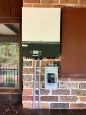
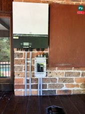
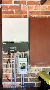
Today's job was mounting the unit to the brick wall.
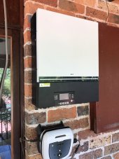
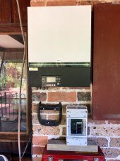
The little box underneath the inverter is my pool robot controller. That will be relocated as I will have cables/conduit and relevant breakers needing that bit of wall real estate.
Mounting the inverter was a bit challenging so to make it easier I went with a French cleat type of solution using two aluminium Z-brackets. I considered using a mounting backboard but didn't think it would look as nice, so I gave the Z-bracket a go.
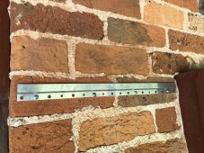
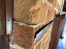
I mounted one bracket to the wall using 4 x 8mm masonry wall plugs and screws. The side on shot shows how the Z-bracket leaves a slot for the other bracket to slide in to. I had to shim a couple of the screws behind the bracket because of the unevenness of the brick - this kept the bracket straight.
The other Z bracket is affixed to the mounting rail at the top of the inverter, with mushroom head bolts, nuts and washers.
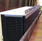
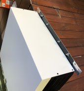
I drilled two extra holes in the inverter's mounting rail to put two extra screws in to affix the Z-bracket securely to the inverter. Nicely tightened with a spanner.
Then I could lift up the inverter so the rail on the top was a little higher than the wall mounted bracket and let it gently slide down into the cleat. Way easier than trying to hold the inverter up while screwing in the mounting screws.
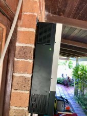
Once it was up I could remove the front lower panel to expose inverter's lower mounting screw holes and use a small masonry drill bit to mark the location of the lower drill holes.
Lift the inverter back up and off the bracket so I can drill those lower mounting holes and insert the plugs. These were smaller plugs, they only need to prevent the inverter from being knocked up and off the top bracket and from being pulled out away from the wall.
Lift the inverter up and onto the bracket again, then screw in the lower mounting points and it's solidly in place.
I note that when removing the inverter's lower panel I need to unplug some fairly fragile looking connectors. So that takes some care. I left those connectors disconnected for now since I'll need to remove that panel again when I do all the cable connections. While there should only be one way to reconnected them, I should have marked them with a sharpie before unplugging to make it clear which side is which when plugging them back in.
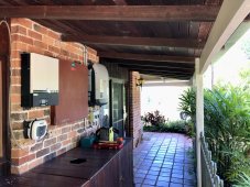
Now while this is technically mounted outdoors, it is well protected under a 2 metre wide eave and doesn't get sun. The other inverter is my Fronius 10 kW Symo 3-phase grid-tied unit. Between them is my main circuit board.
I don't have many options for where else to mount it. It's close to the MCB and while it looks a little impeded for airflow on that side, the MCB is shallower than the inverter and there is still pretty good air flow.
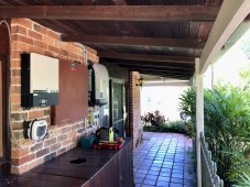
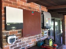
That was enough for today. I'm a bit hammered from a big day yesterday.
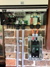
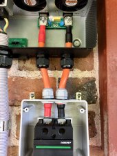
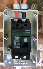
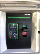
There are numerous next steps but I think first up I'll have a go at mounting the battery's DC breaker onto the wall beneath the inverter. I have a 250 A ZBeny and enclosure and I'll mount the breaker and enclosure directly beneath the inverter right under where the battery cables connect, roughly where shown in the pic below. They are quite chunky units.
I'm going to need some bigger battery cable and suitable lugs as well.
Once I've done that I'll swap all the existing inverter's cabling over so it can at least be functional.
I will have to reconfigure the small off-grid PV array before connecting that. It is currently in a 2S3P arrangement because the smaller inverter has a low 105 V Voc limit, while this unit has a 500 V Voc limit. The 6 x 375 W panels will be fine for one MPPT for now. Later I can add more solar PV, I have the roof space for it.
I'll probably also relocate the PV disconnect to be right under the inverter. Keep it consistent with the grid tied PV system for shut downs. I may add a second disconnect given the inverter has 2 x MPPT inputs.
I eventually plan to make upgrades to the AC circuit side of the cabling. Multiple elements to that.
In the space under where the MCB is I plan for the electrician to install two more circuit board panels (the MCB is full) and reorganise the whole board. I want a separate essential loads panel. Currently that essential/non-essential circuit split is done by the way the wiring to the transfer switch in the MCB is done. It works, is legal, but it's messy and I want the flexibility to be able to move circuits between essential / non-essential in future.
Never ceases to amaze me how long each little part of the process takes but nice to have one bit done.
Since adding the server rack LiFePO4 batteries I've been running the house from this little PIP unit for a couple of months and it's been great. Before that it's been in operation for well over a year doing duty running the pool pump and keeping our backup reserve of lead acid batteries ready for outage backup. It's kept us going through numerous outages.
Since running the house with it we would occasionally experience overloads in the evening, and while the little PIP clone handles that well by instantly switching over to Utility pass through mode, I'd rather it didn't need to do that. I really don't want to be paranoid about every time the wife wants to make some hot tea while she has the microwave going for something else. Plus we have a second occupied dwelling as well which might be doing something similar.
So I have picked up an EASun 8kW SMA MAX unit. The is the same unit as the MPP Solar PIP 8048 MAX.
Today's job was mounting the unit to the brick wall.

The little box underneath the inverter is my pool robot controller. That will be relocated as I will have cables/conduit and relevant breakers needing that bit of wall real estate.
Mounting the inverter was a bit challenging so to make it easier I went with a French cleat type of solution using two aluminium Z-brackets. I considered using a mounting backboard but didn't think it would look as nice, so I gave the Z-bracket a go.
I mounted one bracket to the wall using 4 x 8mm masonry wall plugs and screws. The side on shot shows how the Z-bracket leaves a slot for the other bracket to slide in to. I had to shim a couple of the screws behind the bracket because of the unevenness of the brick - this kept the bracket straight.


The other Z bracket is affixed to the mounting rail at the top of the inverter, with mushroom head bolts, nuts and washers.


I drilled two extra holes in the inverter's mounting rail to put two extra screws in to affix the Z-bracket securely to the inverter. Nicely tightened with a spanner.
Then I could lift up the inverter so the rail on the top was a little higher than the wall mounted bracket and let it gently slide down into the cleat. Way easier than trying to hold the inverter up while screwing in the mounting screws.

Once it was up I could remove the front lower panel to expose inverter's lower mounting screw holes and use a small masonry drill bit to mark the location of the lower drill holes.
Lift the inverter back up and off the bracket so I can drill those lower mounting holes and insert the plugs. These were smaller plugs, they only need to prevent the inverter from being knocked up and off the top bracket and from being pulled out away from the wall.
Lift the inverter up and onto the bracket again, then screw in the lower mounting points and it's solidly in place.
I note that when removing the inverter's lower panel I need to unplug some fairly fragile looking connectors. So that takes some care. I left those connectors disconnected for now since I'll need to remove that panel again when I do all the cable connections. While there should only be one way to reconnected them, I should have marked them with a sharpie before unplugging to make it clear which side is which when plugging them back in.
Now while this is technically mounted outdoors, it is well protected under a 2 metre wide eave and doesn't get sun. The other inverter is my Fronius 10 kW Symo 3-phase grid-tied unit. Between them is my main circuit board.
I don't have many options for where else to mount it. It's close to the MCB and while it looks a little impeded for airflow on that side, the MCB is shallower than the inverter and there is still pretty good air flow.


That was enough for today. I'm a bit hammered from a big day yesterday.
There are numerous next steps but I think first up I'll have a go at mounting the battery's DC breaker onto the wall beneath the inverter. I have a 250 A ZBeny and enclosure and I'll mount the breaker and enclosure directly beneath the inverter right under where the battery cables connect, roughly where shown in the pic below. They are quite chunky units.


I'm going to need some bigger battery cable and suitable lugs as well.
Once I've done that I'll swap all the existing inverter's cabling over so it can at least be functional.
I will have to reconfigure the small off-grid PV array before connecting that. It is currently in a 2S3P arrangement because the smaller inverter has a low 105 V Voc limit, while this unit has a 500 V Voc limit. The 6 x 375 W panels will be fine for one MPPT for now. Later I can add more solar PV, I have the roof space for it.
I'll probably also relocate the PV disconnect to be right under the inverter. Keep it consistent with the grid tied PV system for shut downs. I may add a second disconnect given the inverter has 2 x MPPT inputs.
I eventually plan to make upgrades to the AC circuit side of the cabling. Multiple elements to that.
In the space under where the MCB is I plan for the electrician to install two more circuit board panels (the MCB is full) and reorganise the whole board. I want a separate essential loads panel. Currently that essential/non-essential circuit split is done by the way the wiring to the transfer switch in the MCB is done. It works, is legal, but it's messy and I want the flexibility to be able to move circuits between essential / non-essential in future.
Never ceases to amaze me how long each little part of the process takes but nice to have one bit done.


