diy solar

diy solar

Basic off grid BMS design, for 38 series, 100ah cells; your thoughts wanted.

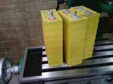
The thirty brand new Winston 60 amp hour cells when they arrived were all within +/- one millivolt , except one cell that was down about 3mV. That cell later failed dead short after about a year in operation. So there must have been something wrong with it right from the beginning.

You will find that in the central flat part of the voltage curve, the cell to cell voltages are always fairly close, its at the ends where the voltages diverge in a really dramatic way.

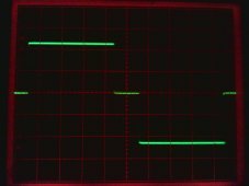
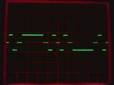
The voltage measurement span is 500mV (3.1 to 3.6v) with 256 bit resolution, so its almost 2mV per bit, but its noise free without any further averaging or processing. Rock steady bars on the screen with the inverter running under load. I am sure nine bit resolution would be possible, but its inconvenient with regards to chip count in a hardware only design, and not really necessary.
If this is to feed into a microcontroller, its definitely stable and noise free enough to do better than eight bits of frequency count resolution.

The most important feature of all this is that its excellent for measuring very small cell to cell voltage differences, rather than having very high absolute voltage measurement accuracy. Same with the cell balancer. Its all rather crude, but self adjusts to have extreme cell to cell voltage sensitivity for balancing purposes.

Earlier on, I had thirty separate voltage sensing circuits, with thirty potentiometers, and thirty discharge resistors. It was hopeless trying to make all of them stay in adjustment. Every single one needs very high ABSOLUTE voltage stability, or they drift all over the place. You will go crazy trying to get it right, and it becomes a cell unbalancer if its not right.
Very glad to get rid of that.
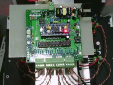
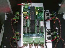
In fact the photograph in an earlier post shows these nightmare cell balancing boards with those evil blue potentiometers.

So Guys, the hot tip is that both voltage measurement and cell balancing should be done by the same circuit located in the central BMS, and used for every cell, rather than trying to do anything individually at each cell. That was a very important lesson that I have learned the hard way.
If something drifts a bit over time in the central BMS, it really does not matter all that much, as every cell still gets the same identical treatment.

Right through all this, I have used 27 ohm one watt resistors as cell discharge loads (125mA). Its not a lot of current but has proved quite adequate for 60Ah cells. But cell discharge loads and balancing needs to be a continuous ongoing process, and the lower the current, the less it will influence cell voltage measurement as it switches in and out.

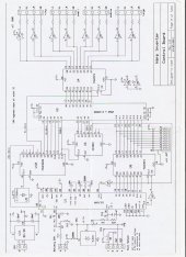
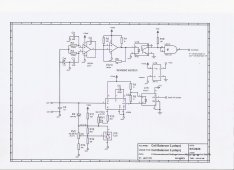
Yesterday I tried to photograph the schematic of the isolated section with my faulty camera, and it turned out horrible. That was really dumb.
I should have scanned it instead, so here is attempt two.
I definitely have an original electronic copy here, and will try to locate that.
 

Attachments

  • BMS isolated section.jpeg
    BMS isolated section.jpeg
    88.1 KB · Views: 8
Last edited:
Your high relative cell voltage accuracy is impressive. How do you detect cell low or high voltage, or is that something you just monitor via your display? I ask as you are limiting the voltage range to improve resolution.

Thanks for the details on your 125ma, 27 ohm balance load.
How old are your 60AH cells now? How much daily DOD?

Sorry for the grilling, but your design experience and LiFePo4 experience with a higher voltage string is extremely valuable!

Bruce
 
I have two separate systems for battery protection.
Individual cell voltages are monitored and if any particular cell hits the high voltage limit, or a low voltage limit, the battery is totally disconnected via a circuit breaker fitted with a shunt trip coil.
The second system does essentially the same thing, in that the main battery voltmeter is equipped with programmable under and over voltage alarms which also trip the same breaker, but it works on total battery voltage, not individual cell voltages.

My cells are now over three years old, and I have had three cells all fail dead short. Not at all happy about that, and I have decided not to double up on lithium cells from 6Kwh to 12Kwh as originally intended. The grand plan now is to purchase one or two reconditioned 48v fork lift batteries. I can get x5 or x10 times the battery capacity for similar dollars to lithium cells.

The battery is very lightly loaded in summer, but winter sees me discharging down to about 30% remaining capacity, well within their capability.
I have no idea why these cells have failed dead shorted. One day working fine, the next day zero voltage. And I mean zero. Not even one measurable millivolt.
The dead cells all had very slight swelling, but nothing dramatic. All a bit of a mystery.
 

Attachments

  • 2020-12-02_0002.jpg
    2020-12-02_0002.jpg
    883 KB · Views: 4
Last edited:
Three premature, sudden LiFePo4 cell deaths in your 100V string is certainly alarming, especially so young and with obviously good care.. I have to watch my ongoing expenses carefully. I stuck with the wet lead-calcium batteries I used for prototype system development even though I had planned on AGM. The wet lead-calcium batteries surprised me by lasting so long and working quite well. 4.5-5 years for $1000 is a bargain compared to my neighbors with 48V, L16 systems. One also disabled neighbor has a copy of my system, and also gets 5 years. We both replaced them last year so we could get a better price on a bulk buy. They are the former Johnson Controls batteries, sold under lots of "Marine Deep Cycle" labels, formerly Everstart, now Diehard. I can only get away with this because of low DOD (lead-calcuim is NOT a true deep cycle) and my BMS. The upside is that lead calcium behave more like AGMs- 100ma or less float current, and water use is very low- a gallon to top all 10 off once a year. I have one 110 AH AGM battery for my house and shop 12V, and it lasts 6.5 years in low DOD, fully-charged-every-day service. AGM's at more than twice the price aren't worth the $ for my main bank, but is handy for one in the shop since I don't have to enclose and vent.

I was interested in LiFePo4 because the the recent drop in cost for bargain cells, and the potential for long service life. You experience seems to indicate long life may still be suspect in the China produced cells. I expect they will get there eventually so I'll keep dabbling on a BMS design. I'm content with my current system, just planning ahead to keep up with the times while I am still able. Lead acid prices keep edging upwards, and lithium is going down.

Thanks for sharing your much valued, higher voltage battery experience and balancer design!

Bruce

PS- Some bad news on true deep cycle wet lead batteries; they use a lot of water and eat about 2 amps of current at float. No kidding, 2 amps at float voltage is normal on a new battery. I do know off grid folks who swear by the big fork lift batteries after a using a few sets of L16s.
 
Another poster on The Back Shed Forum uses 200Ah lithiums in a 48v system and has had two similar cell failures.
We both bought our cells from the same source, and the seller says he has never heard of any similar failures... ever.
However, between the two of us we now have had five dead cells over a two to three year period.
These cells are not cheap, about $3.5K for 6Kwh.

A fully reconditioned fork lift battery 660 Ah and 48v (31.7 Kwh) costs about $3.7K delivered. These are guaranteed to deliver a C5 discharge or 132 amps for five hours, have a full twelve month warranty, and a five year pro rata warranty. The very few people I know that have bought these are completely happy with their battery, and are happy with the seller too.

Although requiring more ongoing regular maintenance, heavy duty fork lift lead acid batteries should also be a lot more robust, and not so easily damaged by the occasional mishap. They can also deteriorate a lot over time and still be perfectly usable with a much reduced capacity.

What I might do is run my 100v inverter on 48v for a while and use a 2:1 voltage step up transformer. If the fork lift battery is as good as claimed, I will buy a second one, although I really cannot afford to do so and makes zero economic sense. But having a reliable trouble free system would be nice.

I will use the exact same BMS, but with a few changes to suit the different voltage range and number of cells. That is just mainly some different component values in the analog section, and re programming several ROMs in the video hardware.
 
Last edited:
One thing to watch out for on transformers; the Antek.com toroidal trannsformers are a great deal and are very high efficiency, but also have very high inrush current; they need to be started with a soft starter or a resistor, then bypass the resistor with a time delayed (1 second) relay. I used them with rewound secondaries for my my inverter, which uses the Trace SW style, secondaries in series method to shape a sine. It had been working great on different toroids, but with the Antek ones (which I switched to for 230V output) was instantly blowing my H-bridge mosfets like crazy until I found the problem. I was able to do soft start via software to fix the problem, with self canceling so no AC ouput until after the transformers were coaxed into normal operation with gradually increasing, alternating polarity pulses. A very educational experience.
 
I am aware of that problem, but have another solution.
I have here a 240v to 240v 20amp 1:1 isolation transformer. I can connect the windings in series and use it as a 2:1 step up autotransformer.
That way, each winding only sees half its nominal rated voltage, flux in the core will be halved and inrush should be just about negligible.

Also using a 5Kw Warpverter type of inverter (of my own design) that has a massive surge capability.
 
I was pleased to find the Trace SW style inverter with dual 1000W transformers has excellent surge; my well pump takes 3500W+ to start, but the inverter starts than an my 230V 1.5HP air compressor just like grid power.
What's the topology of your Warpverter if you don't mind sharing? I figure if you designed it, I can learn something new!
 
The topology is very different to anything else, its something I have slowly developed myself over many years.
It basically delivers a pure sine wave of less than 1% THD, but does not use pulse width modulation.

The idea is that there are four separate low frequency square wave inverters that generate different voltages with the secondaries of the output transformers all connected in series. Its rather like direct digital to analog conversion at the Kw level.
The largest inverter generates a 225 volt peak square wave in the secondary, see picture one. It can produce three voltage levels +225v zero and -225v, three possible voltage steps

The second inverter generates a voltage of one third of the largest inverter +75v, zero, and -75v. If switched at the appropriate times, and added to the largest inverter in generates an output waveform like picture three giving us nine possible voltage steps peak to peak.

Third inverter is one ninth the voltage of the largest inverter, +25v, zero, and -25v see picture four.
When added to the other two inverters we get picture5 and twenty seven steps peak to peak.

Smallest fourth inverter +8.3v, zero, and -8.3v and the final waveform is incredibly smooth with 81 steps peak to peak. See picture six.
Forty steps up, zero, and forty steps down, and less than 1% harmonic distortion. Third harmonic is -40db down.

Peak maximum voltage is 225 + 75 + 25 + 8.3 = 333.3v peak = 235.7v rms.
The transformers have a fixed voltage ratio of course, but by changing the switching points the ac output voltage can be reduced by using fewer but higher steps as the dc input voltage rises.

That is achieved by selecting different lookup tables to adjust the relationship between dc input voltage and ac inverter output voltage.

But the uniqueness of the Warpverter does not end there.
It uses voltage feed forward, not voltage feedback to regulate the output.
The dc input voltage is measured and an appropriate lookup table is selected to keep the ac output voltage constant over a 2:1 input voltage range.

With 256 different lookup tables available, line regulation is almost perfect, within one volt. Load regulation is pretty good too, any voltage sag mainly coming from dc resistance in the transformer windings. Step load response is excellent, as the voltage can be corrected every cycle at the zero crossing point without introducing any waveform distortion.

Rectifying the ac output voltage, smoothing, than applying that to a PID feedback loop is inherently a slow process, and prone to stability issues if you try to speed things up. So light flicker when large motors start up is a far from an unknown problem with most inverters.
Feed forward is very fast and accurate in comparison, and produces far less annoying light flicker.

The slight output voltage droop under load is about 2v/Kw for my own 5Kw inverter, not a lot and quite acceptable.

That slight voltage droop can be completely compensated for, by adding current feed forward as well !

A Hall sensor in the dc feed to the inverter adds some slight extra output voltage correction, so that its possible to have the ac output voltage rise slightly under increasing load if you adjusted it to do that. Response to load change is very fast, and as there is no feedback, no possibility of it ever becoming unstable.

This is a bit of pretty unique engineering I am rather proud of, and it was all originally done with hardware only.
Some of the software guys have now started to get working Warpverter software going and the idea is really taking off.

There are many advantages over PWM, particularly at very high power. All the switching is at a very low frequency so layout is far less important.

There are now about fifteen Warpverters running around the World, all are in the 5Kw to 7.5Kw class so far, but there is really no practical upper power limit. One hero is even now in the process of building a three phase version. Very pleased how its all going, its gained great acceptance.
 

Attachments

  • Inverter#1.jpg
    Inverter#1.jpg
    462.9 KB · Views: 2
  • Inverter#2.jpg
    Inverter#2.jpg
    471.3 KB · Views: 2
  • Inverter#1 + #2.jpg
    Inverter#1 + #2.jpg
    490.3 KB · Views: 2
  • Inverter#3.jpg
    Inverter#3.jpg
    474.7 KB · Views: 2
  • Inverter#1 + #2 + #3.jpg
    Inverter#1 + #2 + #3.jpg
    496.4 KB · Views: 2
  • Inverter#1 +#2 +#3 +#4.jpg
    Inverter#1 +#2 +#3 +#4.jpg
    492.1 KB · Views: 2
Last edited:
My own inverter runs from 90v dc input minimum to 180v dc input maximum. The following waveforms show how a constant ac output voltage is achieved with fewer but taller voltage steps.
The smallest inverter has been disconnected to make the steps coarse so you can see what is happening.
With all four inverters running all the waveforms would be smooth sine waves with nothing obviously different.

Its all rather unusual, but it works amazingly well.
The voltage and current regulation also works when power is reverse flowing from a grid tie inverter back into the battery.
Energy can be pumped back into this inverter without the ac voltage rising excessively which most grid tie inverters don't like.

The only real problem with it is it has zero commercial value.
The cost of four transformers and the high parts count just prices it right out of contention with PWM.

But its much more suited for home construction. If you wanted 5Kw, 10Kw or 20Kw no problem, big slow IGBTs would work fine switching at a few hundred Hz maximum, and the largest inverter only at 50/60Hz.
Trying to build a 10Kw+ PWM inverter to run at 20Khz or more would be very difficult to get going for most people.
 

Attachments

  • regulated steps.jpg
    regulated steps.jpg
    212.6 KB · Views: 5
Last edited:
Often in hardware design, great minds think alike. Your Warpverter design is essentially the same as the later Trace SW series sine inverters except for some details and your four transformers vs their 3. Their patent was granted in in 1994. It's the same method I use in my inverter.


It was one of the first high quality sine inverters with a reputation for reliability and good motor starting capability.

Your Warpverter goes further; The SW used only 3 transformers, each 1/3 the secondary voltage of the last, to shape the sine. They also adjusted the transformer sequence via EEPROM table to get a good RMS voltage with varying DC input and AC load.

I found out about Trace's SW approach in a great technical article above by one of the original Trace engineers describing the history of the US commercial inverter development. My interest was the very low switching rate for this approach, which would allow me to experiment with slow slew rate, semi analog switching of mosfets for very low conducted EMI. My design goal was low emissions, along with wanting good motor life and efficiency. I found a University research paper (I have it but the full paper with diagrams isn't on the web.) which proposed adding another step to a "modified sine" inverter as a cheap way of reducing THD and keeping motors happy. He proved it worked well mathematically to dramatically improve THD on paper but no one ever built one. I used the Trace SW method to implement their concept . My slow switching (45 usecs) causes some bobbles in the waveform during transition for certain transformer secondary subtractions, and transitions, so I found that just adding a second step (5 step total- MSW is 3 step) was best as no transition distortions were created, and THD was better. With fast switching, a perfect sine can be done with your 4 transformer setup. The Trace with 3 transformers managed a THD of 3 or 4%. I had different goals, and my THD is about 12%, better than my generator. It runs at 92% efficiency for a 1000W load, and draws 15W at idle.

I also use the Trace SW method of adjusting waveform timing to get the correct RMS voltage. I use an ATMega 324P in a shielded, filtered die cast box to do the dual H-bridge control sequencing, and select up or down pre-computed table entries based on it's real time sampled RMS voltage. There's a hand wired power and bootstrap board plus the two 1000W toroidal tranformers. It was a real challenge for me, and I couldn't have managed without Modafinil. Alas, now it gives me a headache.

The bugger for me was perfecting the slow switching H-bridge to get a nice fixed slow slew rate without ringing, without frying the carefully selected high voltage mosfets with some linear capability, and to get soft switch whlle avoiding any gate glitching or vulnerability to inverter load generated EMI. I did succeed, eventually. It was very educational.
 
I was aware of the Trace inverter, but did not realise there was a patent, although that does not really surprise me.
I could never find any technical details of the Trace inverter on the internet, and only had a vague idea of how it worked.
I started with this over forty years ago, long before Trace, and others have had ideas along similar lines, so there is nothing new or unique about the concept.
I believe I am probably among the first to use feedforward of both voltage and current for inverter regulation.
Many people have a great deal of trouble even believing its possible to regulate inverter output without having any feedback at all :)
But as we both know, there is nothing particularly new about that concept either.

Engineering is a fascinating subject, many ancient and long forgotten techniques can have some wonderful modern day applications.

I believe Trace eventually went down the drain, a pity, but the reality is that these types of inverters cannot compete commercially with low cost Chinese PWM, and never will be able to. Too expensive to make and too many parts. So this really has no commercial value.

Its a fascinating concept though, and has been a very enjoyable long term development project.
You are quite right about it being very robust, and excellent for motor starting.
It has wonderful characteristics for highly reactive loads too, and is completely bi directional.

My measured THD is actually 0.85% and although the harmonics on my spectrum analyser go on and on, they are extremely low level, and would be quite easy to filter out. I was surprised how much improvement the fourth inverter makes. It seems that although the transformer voltages are all square waves, the transformer currents are all uninterrupted sine waves.
Transformers don't like square wave current, and the fourth inverter was magical in reducing the steps in the current waveform, and all the small discontinuities, overshoot, ringing, and such, just vanished and the final combined voltage waveform went dead smooth.

Over time I have simplified things, and the final iteration uses a dual slope voltmeter for averaging out any noise on the incoming dc.
The voltmeter is triggered every second mains cycle (25Hz) and selects an appropriate lookup table, from 256 available lookup tables. Each lookup table is 1K.
Table switching occurs right at the zero crossing. It could not be simpler. There are four optically isolated H bridges switching four transformers.
Zero load idling power is around 30 watts which is not too bad for a 5Kw inverter.

I have built a few microprocessor versions over the years, but was never entirely happy about the potential for a software crash, and what possible carnage that might do to the power stages. I used some of my wobbly old software to burn 256 different lookup tables in a 256K EEPROM, then went to hardware for better reliability. This inverter has been in continuous operation now for about 3.5 years and has never missed a beat in all that time.

It was vastly easier than this pesky lithium BMS.

Here is the schematic of the complete driver board (drawn by someone else) it includes the feed forward current feature not yet included on my own schematic. Plus the four H bridge inverters with their respective transformers. All quite simple really.
The big IGBTs are 200 amps continuously rated with a half cycle (10mS) surge rating of 1,000 amps.
It will pop a 20 amp C curve circuit breaker on the 240v output easily without raising a sweat.

Do you have any pictures of your own inverter ?
 

Attachments

  • Warp Inverter.jpeg
    Warp Inverter.jpeg
    129.1 KB · Views: 13
  • inverterwiringdiagram.gif
    inverterwiringdiagram.gif
    791.4 KB · Views: 12
  • 2018-06-26_0001.jpg
    2018-06-26_0001.jpg
    1,020.1 KB · Views: 11
  • 2018-10-10_0004.jpg
    2018-10-10_0004.jpg
    941.4 KB · Views: 11
  • 2018-10-10_0001.jpg
    2018-10-10_0001.jpg
    989 KB · Views: 12
Last edited:
I do have some photos and video clips I made for a friend about 4 years ago. Below are some links for short video clips.
The version I'm running now is shown in the installation video. The 12VDC to operate the inverter as installed comes from a secondary winding on one of the output transformers. The installed inverter bootstraps from 12VDC (not 120VDC) as my power shed has a separate 12VDC always available. The H-bridge boards are now using dual push-pull comparators as dual high/low impedence gate drivers. Slow switching of mosfets was a challenging design issue.

I would be glad to share schematics and details privately. I had (hope springs eternal) hoped to somehow make this available for a niche market but I'm just not well enough by mile. Doing design work with serious memory and cognitive deficits is grueling, frustrating, and sets me back seriously. Simple things are just not so simple for me now. MS is a bitch.

https://youtu.be/U36qiYWODBk
https://youtu.be/SK9meMxyLUE

When I made these my internet upload speed was so slow I had to keep them very short and low resolution.

The inverter has served me well and reliably. My Lister CS generator/compressor gets much less run time. I've not had any issues with the prototype inverter and it runs even nasty loads like switching battery chargers without a hitch.

Engineers at Trace Engineering went to Magnum, Xantrex, Midnite Solar. Traces's SW is still remembered fondly by off grid folks. Magnum uses a transformer isolated low frequency design, but not the multiple transformer, secondaries in series method.
 
Since I was a former SW guy, I opted for minimum hardware and my minimalist h-bridge will not block a fatal dead short commanded by software. Not something you'd want to do with a team project. I had to verify the software without 120VDC applied by recording H-bridge command signals on my Picoscope logic analyzer; insuring that a software blooper hadn't happened. Never had a glitch in the 4 years of operation, so far, but my processor is shielded, gets filtered power and data lines and only drives the optos of the H-bridge.

I considered the measuring of DC (input) current and voltage for output voltage adjustment, but had experience with poor PF loads grossly affecting the waveform (top of sine flattened grossly) and AC voltage on a non-RMS generator regulator. I wasn't sure how that might work out, so decided on doing real time AC waveform sampling via a tiny toroidal transformer, full bridge rectified and a bit of low pass filter. The same processor that bangs out the h-bridge table/timer does the sine sampling and RMS calculation between timer interrupts. It works well enough to be within +-2 volts at 230V RMS output.
 
This is all particularly fascinating for me Bruce, because I faced all of the exact same problems, but solved each of them in an entirely different way.

Until now I had zero technical knowledge of the Trace inverter, I had heard that it existed, but that is about all, there is zero information about it on the internet, how it actually works all seems to be a bit of a secret.

You are most fortunate in knowing the people involved, which would have helped a very great deal.

Anyhow, my own design approach to all this was developed quite independently, and probably much earlier, and is free and open source for anyone that is interested.

All the details can be found on The Back Shed Forum, and there are about fifteen Warpverters now successfully running, and several others in the process of being built. The biggest hurdle is winding of the four toroidal transformers, but all the design details are available and plenty of help and advice is available from the Forum.

I know what you mean about cognitive decline, I am in my seventies and its sometimes difficult to remember things.
I am quite happy to just try to help other people, and have no interest in any commercial gains from this.
Its a cruel world, and I am content to be retired and now well out of the competitive rat race.

Its pretty difficult to build a clean EMI free high voltage output square wave inverter, the instantaneous voltage change across a high voltage winding creates massive current spikes that are needed to charge and discharge the unavoidable winding capacitance in the transformer. The result is inevitable voltage overshoot, and ringing. Those current spikes find their way back onto the dc source and can create high conducted and radiated EMI problems.

Your method of slowing everything right down is very clever, and an approach I had never even considered.
But for a nine step inverter its about the only solution that is going to work.
My approach to this was to just add more steps. More steps create a much more sinusoidal current flow in all of the combined secondaries, and that reflects back through all primaries, and even the mosfets (or IGBTs). Each time an extra inverter is added, the waveforms all become cleaner and much better behaved, and the overall EMI becomes less.

The square wave output voltages from each inverter are sometimes adding and sometimes subtracting from each other, and current through each of the H bridges is constantly reversing. Power is surging back and forth, and my solution to that was very tight physical construction with massive and short dc busbars, along with three large very low ESR electrolytic capacitors. Keeping the current loops around the switching bridges very short, significantly reduces radiated EMI. And that is how I approached that particular problem.

The other issue of corrupted mosfet gate drive signals destroying the inverter through cross conduction, were tackled by a unique gate drive circuit of my own design that prevents cross conduction under any circumstances.
Upper and lower mosfets are driven via the usual optically isolated gate drivers, but the trick is to connect the LEDs of the two opto isolators in inverse parallel. Its then just not possible for both to be on simultaneously.
That is driven through a balanced twisted pair cable , and the whole thing has excellent noise immunity, even with very long unsheilded opto isolator drive wires.

There are now at least four different driver boards available for this. My own original hardware board, another similar hardware board with current feed forward correction included, and two more from different people with different software that both use nano microcontrollers. All boards use the same plugs and sockets and pin outs. So its become a fully standardised open source plug and play exercise. All these controller boards offer identical performance, and without actually looking, I am not actually sure what is in my own inverter right now !
They all do exactly the same thing.
 

Attachments

  • 2019-05-07_0001.jpg
    2019-05-07_0001.jpg
    750.1 KB · Views: 6
  • 2019-05-07_0002.jpg
    2019-05-07_0002.jpg
    725.5 KB · Views: 6
Last edited:
I didn't know the engineers at Trace, just found some articles on the web about the early US inverter market and then studied the Trace patent.
That's great that your design is being used an is growing in popularity on The Back Shed. I found some articles referencing your Warpverter. How did you manage that?

My EMC studies have banged it in my head; use conservation of bandwidth whereever you can as EMI = Current X Current Loop Area X Frequency. I try to work the "conservation of bandwidth" angle whenever I can. In the case of my inverter I had to pick in inverter topology with the lowest speed and least amount of switching possible so I could successfully use slow slew rate switching with linear rated Mosfets. When I first started using the soft switching trick in 2009, there were no SOA ratings for mosfets except the IXYS P-channel; you just had to pick a high voltage rated Mosfet and test it to see what it could take. Now SOA data is readily available, and is quite decent on the higher voltage mosfets.

In recent years I've found that some of the newer extremely low power op amps and comparators with very bandwidth and low slew rates are quite a simple and marvelous way of implementing ultra low EMI circuits. Astonishing to have these parts drawing under 10uA, while giving the the nice soft slew rate I wanted but didn't have to design in.
 
I found some articles referencing your Warpverter. How did you manage that?
The idea was slow to catch on initially, but over time it has caught some attention, and its now taken on a life of its own.
I am not trying to actively promote this, there is really nothing in it for me, except the very great satisfaction of seeing others complete a successful home brew high power inverter project.

Its been a fantastic learning experience, and that is reward enough.
Also helping others has really great Karma about it.
 
Last edited:
Back
Top