Boy! I am not very good at doing updates...
I have been using the batteries for about 6 months now. No problems (other than my own stupid mistakes that I will list below).
A few other updates first - Heating.
Because my motorhome batteries (starting & lithium) are basically outside, I built in a RV tank heating pad under the batteries. I have a 1/2" plywood for the base of the battery box, then is the RV tank heater pad. Side-to-side it fits but it was about 3 to 4" too long - so it sticks out the front. Because the heater pad in designed to stick on RV holding tanks, one side was very sticky. I didn't want the sticky mess getting on the batteries (wanted to remove the batteries if needed), and I also wanted an extra electrical insulator, I got a couple of sheets of MICA from amazon (Mica is an electrical insulator, but also allows good thermal conductivity - it is usually used in the microwaves). I stuck the Mica to the heating pads. The sides of the box is 3/4" plywood with a plexiglass top (plus a couple of fan holes and holes for buss bars). I used foam and sealed up the battery bay as much as I could - but it is a metal box exposed to the outside.
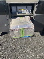
When it started to get cold in the fall, the temperature of the Victron SmartShunt was warmer than the outside by only about 5 degrees in the morning. I wanted the batteries even warmer, so I got some foil insulation (the kind that looks like plastic bubble wrap covered in aluminum foil), and taped together a cover to go over the battery. I also used masking tape to cover the inside of the cover because I noticed the foil insulation would conduct some electricity.
Since adding the cover, the batteries stay much warmer. Probably because the heat that is generated gets trapped inside the insulation cover - instead of just escaping. I call the heating part of this project a SUCESS!
Update - Communications between Batrium & Victron.
I have not yet connected the communication wires between the Batrium & the Victron CCGX. Busy, Lazy, other projects, and it is working just fine without it. At first I could say I didn't have the wire in place... but I can't use that excuse anymore. Because the charging is working very well without the communications, I have not felt the need to get it done. Funny how I was so sure I was going to use this and now it just a maybe.
Path of Woe. First let me state it's all my fault! As we were getting ready to head out after installing the lithium battery, I went through and checked all the fluids (good right!). Well I checked the starting battery and noticed the cells were a bit low on water. So I got some distilled water and topped them up. After a short run, I was checking on the lithium battery and I noticed drips on the BMS! The starting battery and bubbled some acid out and it was dripping on my new lithium battery!!! (The starting battery sits just above the house batteries). I cleaned it up the best I could. Now I was really MAD at myself, because when I started this project I decided to replace the 2 year old starting battery with an AGM battery. I had forgotten to do that. So I ordered the 8D AGM starting battery, and cleaned everything up the best I could. The BMS was still running just fine.
About a week or so later we were camping and all of a sudden weird things were happening with the power. The 12v was flickering at strange times and I could hear a click. I soon realized the BMS was shutting off for a moment then back on. Because we had good sun, the solar was running the rig. it kept doing that for longer periods. I plugged the computer into the batrium and found out it was losing connection with its shunt. At this point I was comfortable running the system , so all I could do was set the contactor to run continually and run without a bms. I ordered a new set of everything. (The Batrium Core was now available). Got it - installed it and its been running great. This bummed me out for a while.
Future Updates:
Someday I may have the batrium control the charging through the cam buss, or maybe I will just enable the 2-wire bms assistant in the victron and use some of the extra relays to run that.
Another idea is to get a small intel nuk computer with a 7" screen and have it display the batrium software all the time. I have a great place next to my CCGX.
I have been using the batteries for about 6 months now. No problems (other than my own stupid mistakes that I will list below).
A few other updates first - Heating.
Because my motorhome batteries (starting & lithium) are basically outside, I built in a RV tank heating pad under the batteries. I have a 1/2" plywood for the base of the battery box, then is the RV tank heater pad. Side-to-side it fits but it was about 3 to 4" too long - so it sticks out the front. Because the heater pad in designed to stick on RV holding tanks, one side was very sticky. I didn't want the sticky mess getting on the batteries (wanted to remove the batteries if needed), and I also wanted an extra electrical insulator, I got a couple of sheets of MICA from amazon (Mica is an electrical insulator, but also allows good thermal conductivity - it is usually used in the microwaves). I stuck the Mica to the heating pads. The sides of the box is 3/4" plywood with a plexiglass top (plus a couple of fan holes and holes for buss bars). I used foam and sealed up the battery bay as much as I could - but it is a metal box exposed to the outside.
When it started to get cold in the fall, the temperature of the Victron SmartShunt was warmer than the outside by only about 5 degrees in the morning. I wanted the batteries even warmer, so I got some foil insulation (the kind that looks like plastic bubble wrap covered in aluminum foil), and taped together a cover to go over the battery. I also used masking tape to cover the inside of the cover because I noticed the foil insulation would conduct some electricity.
Since adding the cover, the batteries stay much warmer. Probably because the heat that is generated gets trapped inside the insulation cover - instead of just escaping. I call the heating part of this project a SUCESS!
Update - Communications between Batrium & Victron.
I have not yet connected the communication wires between the Batrium & the Victron CCGX. Busy, Lazy, other projects, and it is working just fine without it. At first I could say I didn't have the wire in place... but I can't use that excuse anymore. Because the charging is working very well without the communications, I have not felt the need to get it done. Funny how I was so sure I was going to use this and now it just a maybe.
Path of Woe. First let me state it's all my fault! As we were getting ready to head out after installing the lithium battery, I went through and checked all the fluids (good right!). Well I checked the starting battery and noticed the cells were a bit low on water. So I got some distilled water and topped them up. After a short run, I was checking on the lithium battery and I noticed drips on the BMS! The starting battery and bubbled some acid out and it was dripping on my new lithium battery!!! (The starting battery sits just above the house batteries). I cleaned it up the best I could. Now I was really MAD at myself, because when I started this project I decided to replace the 2 year old starting battery with an AGM battery. I had forgotten to do that. So I ordered the 8D AGM starting battery, and cleaned everything up the best I could. The BMS was still running just fine.
About a week or so later we were camping and all of a sudden weird things were happening with the power. The 12v was flickering at strange times and I could hear a click. I soon realized the BMS was shutting off for a moment then back on. Because we had good sun, the solar was running the rig. it kept doing that for longer periods. I plugged the computer into the batrium and found out it was losing connection with its shunt. At this point I was comfortable running the system , so all I could do was set the contactor to run continually and run without a bms. I ordered a new set of everything. (The Batrium Core was now available). Got it - installed it and its been running great. This bummed me out for a while.
Future Updates:
Someday I may have the batrium control the charging through the cam buss, or maybe I will just enable the 2-wire bms assistant in the victron and use some of the extra relays to run that.
Another idea is to get a small intel nuk computer with a 7" screen and have it display the batrium software all the time. I have a great place next to my CCGX.
Last edited: