diy solar

diy solar

Batteries, BMS, Heat, and Wiring (3x100AH vs 1x300AH, 12v)

after1985

New Member
Joined
Apr 5, 2022
Messages
21
I'm considering getting about 300AH of 12v battery(ies) for my RV. Currently I have 1x100AH Ampiere Time 12v, a Victron 12/3000 inverter, and 4/0 wiring where it makes sense.

The BMS on the battery maxes out at 100A continuous (rated), so I figured I'd run a max test with the A/C turned on. I had it run for about 15 min, drawing anywhere from 100-130A according to my smart shunt. I noticed the positive terminal on the battery got quite hot to the touch, but the rest of the battery felt cool.

Now, running the A/C on a 100AH battery with a 100A BMS is not a good idea, I know, so I'd like to either get a total of 3x100AH batteries OR 1x300AH battery (with a 200AH BMS).

My question is, if I do 3x100AH and wiring them in a diagonal config (see picture from Victron guide), will I still have the same heat problem on the positive terminal that feeds the rest of the system, even though I could theoretically use 300A of continuous current with that configuration? It seems to me the heat problem on that terminal might even be worse, since 300A of current might flow through the internal battery wires (6AWG?) and the terminal.

Without seeing a teardown of the 300AH Ampiere Time battery, I'd think that the internal wiring would be beefier if it has a 200A BMS, so heat wouldn't be as much of a problem.

Next question: If my above concern is valid - heat buildup in diagonal config - should I just use the "Posts" or "Busbars" configuration to mitigate that?
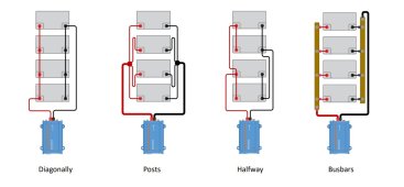
VictronWU.jgp.jpg
 
Now, running the A/C on a 100AH battery with a 100A BMS is not a good idea, I know, so I'd like to either get a total of 3x100AH batteries OR 1x300AH battery (with a 200AH BMS).
3000 ac watts / .85 conversion factor / 12 volts low cutoff = 294.117647059 service amps
294.117647059 service amps / .8 fuse headroom = 367.647058824 fault amps.
In order to use 4/0 pure copper wire with a 400 amp fuse you need to set the inverter cutoff to 12 volts.
Practically that means an inverter charger as discrete inverters generally don't have a configurable low voltage cutoff.

A 200 amp bms won't cut it.
So you need 3 batteries each with a 100 amp bms and the path resistance must be perfect.
The best method for this is posts.
You can also do posts on the negative side and connect each positive to a fused busbar.
I can explain more if necessary.


Would you mind explaining a bit more regarding your first paragraph of your reply? I have a victron inverter-charger with low voltage cutoff parameters. Are you saying I can’t use a 400A fuse unless I see that to cutoff at 12.0v? Though under the best practice rating, would a 350A fuse meet the other requirements?

Regarding the second paragraph, why not 200BMS? I basically need 1200-1500w max for my A/C to run on high. Even accounting for efficiently and conversion losses, wouldn’t 200a be more than enough? I realize the inverter is “250a”/3000w capable, but I can’t see how I’d get close to that except for surge when starting the A/C. I’m only using that inverter because I got it brand new in the box for $300.

I was more concerned with the heat issue and how to two battery options affect it, but I appreciate any and all feedback. I’m still very green to all this, so please let me know what I’m missing.
 
Would you mind explaining a bit more regarding your first paragraph of your reply?
I see now that you have a victron inverter_charger.
That changes the math.
They are rated in volt amps not watts.
3000 ac volt amps ~= 2400 ac watts
2400 ac watts / conversion factor / 12 volts low cutoff = 235.294117647 service amps
235.294117647 service amps / .8 fuse headroom = 294.117647059 fault amps
I have a victron inverter-charger with low voltage cutoff parameters. Are you saying I can’t use a 400A fuse unless I see that to cutoff at 12.0v?
Since its a Victron inverter-charger I suggest you set the low voltage disconnect on the inverter to 12.0 volts to avoid unnecessary wear and tear on your battery.
12 volts(3.0 volts per cell average) is the apex of the low knee.
That means most of the cells will be starting to freefall towards empty.
One of the cells will be the weakest and it will drop off first.
Over time the weak cell gets even weaker from being discharged further than the others.
The cell temperature rises a bit at the end causing a bit more stress.
Also opening the BMS discharge FETS at significant current is not something that should happen except in an emergency.
FETS have a tendency to fail closed meaning that the BMS can't protect anymore but appears to operate normally.
Though under the best practice rating, would a 350A fuse meet the other requirements?
Victron wants 4/0 awg with 400 amp fuse, I think you should do that just in case you ever need Victron support.
That is for the inverter circuit.
Regarding the second paragraph, why not 200BMS?
Its my policy to design the system to handle the full continuous rating of the inverter.
I realize the inverter is “250a”/3000w capable, but I can’t see how I’d get close to that except for surge when starting the A/C.
It can pull 282.352941176 amps at 10 volts and 235.294117647 amps at 12 volts.
I was more concerned with the heat issue and how to two battery options affect it, but I appreciate any and all feedback.
What heat issue?

You can parallel things very nicely with 2 lynx power-in units connected by their backplane.
This video will show you how to put fuses for the branch circuits.
Branch circuits are for the inverter, other loads and other charge sources.
The batteries are the feeder circuits and get fused at the battery positive and not at the busbar.
The batteries each get 4 awg with a 125 amp MRBF fuse.
The 4 awg battery negatives all bottleneck through the shunt and a 4/0 wire to the busbar.
 
@after1985 , the posts or bus bar wiring method is my preference.

The diagonal method will work, but you have to adjust where the leads tie into the cables between the batteries. The optimization of this position isn't simple. There is a thread in the General Discussion forum that uses a lot of math behind the scenes to prove the optimal location.

Hot spots under load often indicate a poor connection. Clean the contact surface well and ensure they connection is tight. Maybe you have a bad crimp?
 
I see now that you have a victron inverter_charger.
That changes the math.
They are rated in volt amps not watts.
3000 ac volt amps ~= 2400 ac watts
2400 ac watts / conversion factor / 12 volts low cutoff = 235.294117647 service amps
235.294117647 service amps / .8 fuse headroom = 294.117647059 fault amps

Since its a Victron inverter-charger I suggest you set the low voltage disconnect on the inverter to 12.0 volts to avoid unnecessary wear and tear on your battery.
12 volts(3.0 volts per cell average) is the apex of the low knee.
That means most of the cells will be starting to freefall towards empty.
One of the cells will be the weakest and it will drop off first.
Over time the weak cell gets even weaker from being discharged further than the others.
The cell temperature rises a bit at the end causing a bit more stress.
Also opening the BMS discharge FETS at significant current is not something that should happen except in an emergency.
FETS have a tendency to fail closed meaning that the BMS can't protect anymore but appears to operate normally.

Victron wants 4/0 awg with 400 amp fuse, I think you should do that just in case you ever need Victron support.
That is for the inverter circuit.

Its my policy to design the system to handle the full continuous rating of the inverter.

It can pull 282.352941176 amps at 10 volts and 235.294117647 amps at 12 volts.

What heat issue?

You can parallel things very nicely with 2 lynx power-in units connected by their backplane.
This video will show you how to put fuses for the branch circuits.
Branch circuits are for the inverter, other loads and other charge sources.
The batteries are the feeder circuits and get fused at the battery positive and not at the busbar.
The batteries each get 4 awg with a 125 amp MRBF fuse.
The 4 awg battery negatives all bottleneck through the shunt and a 4/0 wire to the busbar.


Thank you for the reply. That all makes better sense to me now.
 
Back
Top