Ok, it’s been a few interesting days, did an audit to the 2 fridges and the freezer chest for about 90 hours, all 3 came down to a combine use of 124 watt hours, also had a brand new mini split a/c that when is on and cooling it draws 6 amps, but when it has cooled the room down it goes down to a 1.5 amp draw, I see this on the amp meter I have on the dedicated load center just for the solar fed breakers, I also had my bedroom with closet, and bathroom lights, a couple night stand lamps, the internet modem and wifi router, smoke detectors, flat screen tv with Apple TV, electronic Hornady handgun table top safe, ( just a one or two handgun size) fed with a small wall transformer, and alarm clock, keep in mind that all those lights will not come on at the same time and when they do, they will not be on for more than a couple hours at night, haven’t done a audit on the TV, the Apple TV night stand lights and rest of the plug in stuff.
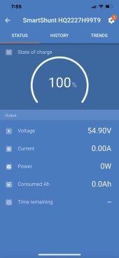
First night after solar panels charged the batteries up to 100% all was fine, next morning I was just down to 84% on the Epever but the Victron shunt was at 98%, (makes no sense to me), by 9:00am the Victron showed 100% and the Epever was at 95%.
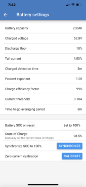
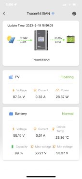
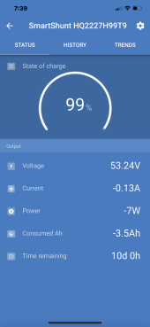
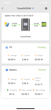
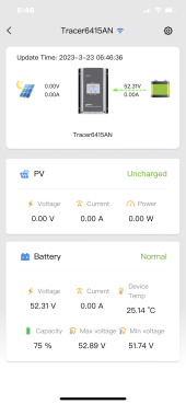
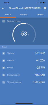
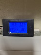
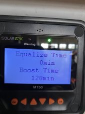
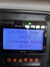
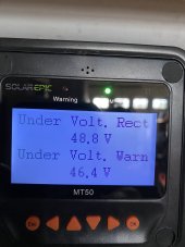
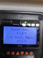
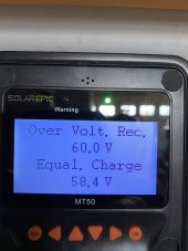
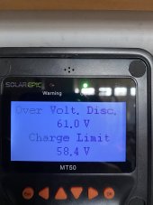
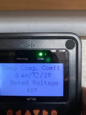
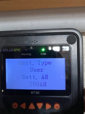
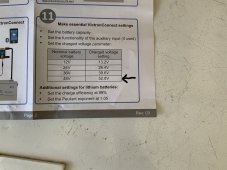
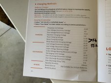
Last night I ran all the same things just like the night before with the mini split on all night, and at 6:45 this morning I noticed the ceiling lightbulbs (which are all LED by the way, where showing a very dim amount of light, I mean, so dim that you could only see it in the dark, the mini split display also had a really really dim amount of light coming from the display, I figured all these led’s were running low on power, so I got up and checked the meter I have on the load center and it was showing 123 volts and using 2.69 amps, see first picture, (no reason to me for the led bulbs to be acting up like that, then I changed to grid power, all went back to normal, but at that moment the Victron was showing 53% Stage of charge, see 2nd pic, and the Epever was at 75%, pic. 3, I’m sooooooooo confused., you have all seen the settings on the Epever and Victron Shunt, I don’t seem to find an explanation for such discrepancies. Also attached is a pic, #4 on the battery settings of the Victron Shunt. And on the Epever, on therest of the pics, on another reply, since I can’t post so may on one reply.
I decided to start from scratch and individually charge each battery with the 14.6 volt 20 amp charger, equalize them and go at it again.
If anyone have advices on the Epever and Victron Shunt combined settings, I’ll apréciate any inputs.
Thanks all.