diy solar

diy solar

Batteries in series not charging evenly.

The batteries may have different actual (as opposed to rated) amp/hr capacities.
Yes, they are likely different, I am trying to learn about each of them.
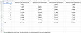
I reread the thread and craig's cells are, by your explanation, in ascending order of capacity. If randomly selected, I think the odds of that are 12! : 1 (close but not quite exact, sorry).

My cells are, by your explanation, in descending order of capacity. I mistakenly said my order was the same as his, its actually the opposite. This is more troubling to me at the moment. Odds 4! : 1

I think I will equalize them, reverse the order and see if the trend line reverses. (i'm not sure what i'm hoping for!)

Being wired in series, they will all get the exact same charging current,
I am a little surprised, I would have expected the internal resistances of cells as they progress from 1 upward to have "some" effect on the charging current in subsequent cells (and consistent from one series of cells to another). I rather like the idea that they are exactly the same, it simplifies things quite a bit.
 
Last edited:
I think you are just either not charging fast enough for the draw on them (if any), not waiting long enough for things to equalize, or the bus bars/charge wires are too small.

Last week I decided to charge up an old, but still good, bank of four 100ah lead acid batteries I had stored in the shed unconnected for months. They ranged from 12.2-12.5. I hooked up a 1 amp (!) battery tender to the first one, then connected the rest in parallel with tiny 22awg (!) jumper wires with alligator clips on each end. Yes, 22awg on 4 honking big batteries at 1 amp. Anyway, the first battery that the charger was hooked to was charged the first day and each battery down the line was slightly less charged than the one before it. Each day the next battery would reach full, then the next etc... So it took a while, but they all equalized at full SOC and at the same float voltage the tender was putting out (13.4ish).

This wouldn't have happened if the batteries were connected with 2 awg (the way they normally were), but it happened with 22awg. Sooo...does your BMS charge through the tiny sense wires or is it charging through the actual buss bars like it should?
 
If it were me I'd make a set of short 10awg jumper wires with alligator clips on each end, they will come in handy for other projects anyway. Use the jumpers to double up on your aluminum bus bars. If the problem goes away you know your bus bars are the problem...
 
I am charging directly from the charge controller. They are brand new, this is their first charge. The arrived at 3.24v each.
No BMS, direct connect with alligator clips as pictured.
I am watching the voltages with an ISDT BatGo without balancing enabled.
I did a bottom balance at 3.24v, (i did not record the 3rd decimal place) which the ISDT said was 19%.
Never had a load on them. I am going to perform an internal resistance test on them with a 1 ohm resistor shortly (the Tenergy 5 in 1 unit's internal resistance test produces bogus results, there is a thread on that too).
 

Attachments

  • IMG_1447.png
    IMG_1447.png
    486.1 KB · Views: 11
Use the jumpers to double up on your aluminum bus bars. If the problem goes away you know your bus bars are the problem...
My bus bars are tinned copper. I like the idea of doubling up on them. They are the ones that I bought from the battery maker but they were a little smaller than i expected. But they are copper.

I have a few things to try, thanks!. My setup is pretty simple so i should be able to get some answers with only a little effort (i really need the clouds to get out of the way of my power supply!)
 
I was referring to the OP's aluminum buss bars. I don't think your few mV difference is a big problem....maybe will just take a bit longer to equalize? Not sure...
 
If there is no active balancing going on then your few mV difference between cells is to be expected.
Ok, thanks. Just trying to learn and noticed a pattern...

I just realized (from my pic!) that my setup is not as i described. I have my +/red charge clip on cell 4 and -/black on cell 1. So my decreasing voltage pattern is the same as craig's though smaller. Odds of us both randomly selecting batteries and placing them in decreasing order is a little over 11 billion : 1.

I'll reverse the charging and will chime back in with results.

I hope I did not hijack craig's thread too much, but we are clearly experiencing the same "series not charging evenly" pattern.
 
No hijack its all good reading.. I am a little interested though in the difference between parallel charging and series charging. It makes sense that the first battery in paralell will draw more power than the 4th cell if connectors are not large enough.

It seems to me in series it would be a totally different scenario since the energy goes through all of them all the time.


attached below is my individual cell testing data from 4 cells I tested today they are all rated at 40Ah and all achieved above that in capacity however at which voltage the energy is produced varies from cell to cell. This could lead to balance issues.

What I am not sure about is how big of a problem this is as long as the BMS can cut off charging and discharging before any cell gets too high or too low. the cells may be off in the middle voltage ranges but at the top and bottom they should closen up.
 
attached below is my individual cell testing data from 4 cells I tested today they are all rated at 40Ah and all achieved above that in capacity however at which voltage the energy is produced varies from cell to cell.
Sorry but I cannot figure out what you are doing here. The numbers represent the calculated or measured "amps produced"? And totaled?
 

Attachments

  • Screen Shot 2019-12-27 at 7.29.37 AM.png
    Screen Shot 2019-12-27 at 7.29.37 AM.png
    98.3 KB · Views: 3
The total amp hours each cell produced is at bottom
You ran your batteries down to 1.6 volts? That can't be good for them.

And how does the first battery "produce" (still not sure what that means) 15.2ah
at 2 volts and then 3.8ah at 1.9 volts? I am way lost on what these numbers represent. How do amp hours increase as you go from 2.5v to 2v and then drastically drop from 15.2ah to 3.8ah as you discharge to 1.9v?

I'm missing something, sorry.
 
These are Lithium Titanate cells there range is 1.5 to 2.9 volts. And yes those numbers are the actual amounts if energy produced at a .3C discharge rate.
I test the batteries under a load and record the amps being drawn and the batteries voltage every 15 seconds. I then add up the readings to get amp hours produced at each voltage level.
 
UPDATE - looks like I misunderstood the original post as to the voltages. My post below would be the case if the TOTAL voltage drop across each cell were the .05 difference they're seeing per cell. Different situation.

I'm totally new (1st post!) but wanted to chime in on a fairly basic level to the original concern and see what you all think.
He's dropping .05V per cell and charging at 20A, correct? So E/I=R means he has .0025 or 2.5 milliohms per cell.

My question is, is such an internal+wire resistance acceptable (seems pretty small), and just a hazard of series configurations? Is it then just a matter of time waiting for each cell to complete charging as someone mentioned earlier?
 
Last edited:
Back
Top