diy solar

diy solar

Battery Bank Disconnect Switch for large off-grid system

Why are you using 2-pole breakers? That's for 240VAC. Midnite Solar has a disconnecting combiner box designed specifically for combining lithium batteries. Use the right product for the job. You'll need multiple, as they are for 10 batteries, but it's cheaper than the alternative of a fire. https://www.midnitesolar.com/produc...e=Combiners&productCat_ID=9&sortOrder=1&act=p
The simple reason is single pole Square D breakers are rated to a maximum of 48V. If you are using batteries capable of being charged up to 64.8V, you certainly don't want to use one without the capacity to carry the voltage.
 
So I was pleasently surprised to see the SquareD QO has a DC rating.... Great find!!!

I copied the following from the spec sheet:


Voltage Rating
The circuit breaker must have a voltage rating greater than, or equal to, the system voltage. When a
circuit breaker clears an overcurrent, it is done in two steps. First, the current sensing system identifies
the overcurrent and releases the tripping mechanism. This results in a parting of the contacts. The
circuit breaker must then extinguish the voltage arc across the contacts. If the circuit breaker has the
correct voltage rating, it can efficiently extinguish this voltage arc. QO and QOB circuit breakers are
rated for use in the following voltage systems:
• 120 Vac
• 208/120 Vac
• 120/240 Vac
• 240 Vac

• 48 Vdc (10–70 A for 1 and 2 pole circuit breakers, 10–60 A for 3 pole circuit breakers)

They look like great alternatives for 12 & 24V systems, but would not use them in a '48V' system. 48 Volt systems can get up to 58V on LiFePO4. In fact, the voltage will almost always be above 48V on the system.

In this thread there was a least hints that by putting breakers on positive and negative, it is ok to use the SquareD QO because both sides will break. I can not buy into this. These are mechanical devices and one of the two breakers will always break a fraction of a second before the other and will take the full brunt of the disconnect. Likewise, on connect, one of the two will connect a fraction of a second before the other.

A breaker is a safety device.... and safety devices are *not* where you want to fudge and say 'close enough'.
 
Square-D says (several of their) 2-pole branch breakers are good up to 125VDC if both poles used to interrupt positive and negative.
So I think that means one pole is actually fine up to 62.5VDC. The larger main breakers are NOT rated for DC, however.

Yes, when mechanically linked they break a fraction of a second apart. That is probably OK, still do their job.
When an AC rated breaker opens, current flows in the arc up to 1/120th of a second until zero crossing. That's 8 milliseconds.
The ganged DC breaker would arc and burn for a moment, then interrupt when voltage is split across the two.

In house wiring, the main breaker is rated 22kA interrupting, and the branch circuits 10kA. In the event of a short, both can open but the branch may not be able to interrupt the current and the main does so. Fast enough to prevent the branch breaker from exploding.

"Current limiting" fuses don't limit the short circuit current, rather the time. With 100,000A short circuit current, a class-T fuse will blow so fast that a breaker in the current won't get more energy deposited than it would have with a 10,000A short, and so it is protected from blowing up. Probably doesn't work again, however.

The QO breakers are non-polar, so I think good for a PV combiner below 125Voc.
I have a problem with polar breakers being used in a combiner box, because they only work for current flow in one direction but combiner box use requires that they function with current flowing both directions.

For OP's situation of combiner box for batteries, it obviously requires ability to trip for both overloads and fault currents in both directions. A polarized breaker would not work. The QO breakers in a panel appear to meet the need at first glance. Possible problem I see is relatively low AIC, about 5000A. If one battery string shorts and all the others dump into it, short circuit rating of the breaker for failed battery won't be able to interrupt the current. Each of the other breakers would need to independently trip. If < 5x their rating, this would take too long (thermal trip). Would have to be > 5x their rating for instant magnetic trip. Depending on wire resistance, that may not be the case.
 
So this is what the document says.

The QO single Phase Main Lug Load Centers are SQUARE D CERTIFIED for use on 125 V DC systems. The load centers listed ARE NOT MARKED for use on this voltage system, however are suitable for the application. The positive (+) conductor should be connected to one phase lug, while the negative (-) conductor should be connected to the other phase lug. USE QO 2-POLE BRANCH BREAKERS ONLY. QO branch breakers, 10-70 ampere, are also SQUARE D CERTIFIED for use on 125V dc systems. Short circuit current rating is limited to 4,000 amperes (10-30 ampere) or 10,000 amperes (35-70 ampere) when used on 125V dc.

That is great news. It opens up options for 48V systems. (I wish it was stated in the data sheet. In a separate note like that is not as definitive)

However, notice the "USE QO 2-POLE BRANCH BREAKERS ONLY.".

I would not leap to the conclusion that you can do 62.5 V with a single pole. If this were the case, I would think the spec sheet would say that, but instead it says 48V. I am guessing that they are counting on the second contact opening quickly enough to minimize the duration of the arching on the first breaker. On a single breaker, they can't count on the second 'break' so they spec a lower voltage.
 
I tend to leap. At least if I don't have to get something approved by someone who's a stickler for the documentation.
But sometimes I pause in mid-air to ponder the consequences.

Wile E Coyote cliff.jpg

On one hand, if two poles can interrupt 125VDC, absolute best case is each pole interrupts 62.5V by itself. Otherwise, one gets more and the other gets less.

On the other hand, maybe each pole can interrupt 48VDC regardless of polarity (as per UL listing).
But, due to it's characteristics for extinguishing an arc, it can interrupt more in one direction only.
By using QO 2-pole breaker only, the two poles carry current in opposite directions. One is guaranteed to be in the better direction.

This is where I question Midnight's assertion that their polarized breakers are good for use in a PV combiner box.
When being used to shut off the array with current flowing in the normal direction, that matches the polarity they have demonstrated in lab tests.
When used to interrupt a fault current backfeeding one failed PV string with current from all the other PV strings, it will be called upon to interrupt current flowing in the abnormal direction. Midnight has demonstrated the breaker will burn in that situation.
Yet, they say their polarized breakers can be used in a PV combiner.
I say, "Only if all the breakers are mechanically ganged so when one trips, it turns off the others."
 
Polarized breakers will trip with the current going in either direction. They are polarized because they use a collapsing magnetic field to 'blow out' the arc.... but it only works for current going in one direction.

In practice, this means that the breaker can safely handle a smaller current in the opposite direction. In a solar setup, it is usually the case where the max current on a battery is greater in one direction than the other (Usually discharge is much greater). So...it might be possible for a directional breaker to function well. However, I have never seen 'reverse current' ratings on directional breakers so I would be hesitant to count on it. (Since it is a safety device....I don't want to make assumptions)

Along these lines..... I used to be a 'breaker-for-everything-and-no-fuses guy. I wanted to always be able to reset and move on. However, I have changed my mind over time. If I have a current of 150A in normal operation, it better not blow a circuit in anything but a catastrophic failure. (If you routinely blow a 150A circuit.... the design is really bad). Consequently, for anything over about 50 Amps I use fuses. They are lower cost and their simplicity makes them very reliable.
 
My system has 6x 100 amp Westinghouse type FB breakers for my PV Output combiner, that then has a 400 amp feed going to my batteries. THese breakers are rated at 10,000AIC at 250vDC
 
Polarized breakers will trip with the current going in either direction. They are polarized because they use a collapsing magnetic field to 'blow out' the arc.... but it only works for current going in one direction.

In practice, this means that the breaker can safely handle a smaller current in the opposite direction. In a solar setup, it is usually the case where the max current on a battery is greater in one direction than the other (Usually discharge is much greater). So...it might be possible for a directional breaker to function well. However, I have never seen 'reverse current' ratings on directional breakers so I would be hesitant to count on it. (Since it is a safety device....I don't want to make assumptions)

Along these lines..... I used to be a 'breaker-for-everything-and-no-fuses guy. I wanted to always be able to reset and move on. However, I have changed my mind over time. If I have a current of 150A in normal operation, it better not blow a circuit in anything but a catastrophic failure. (If you routinely blow a 150A circuit.... the design is really bad). Consequently, for anything over about 50 Amps I use fuses. They are lower cost and their simplicity makes them very reliable.

Midnight's test put 99A at 165V through a 63A 150V breaker. I think they manually switched it off after 1 second, before the magnetic-hydraulic delay tripped. In one direction it passed, but in the other direction if failed (rather spectacularly)


So that test was 10% over in voltage, 50% over in current.
I think that to interrupt current backflowing into a PV string, it could only work if wired for that polarity (opposite of recommendation). In that case it might be usable as a switch so long as no faults, because would normally have a smaller voltage (just Voc - Vmp) to interrupt. But not necessarily in the event it was feeding a short (Isc followed by Voc).

Wiring two of them in series (opposite polarities) would work up to 150V. Wired in same polarity for 300V, same issue as before.

Midnight has some impressive interrupt ratings (50kA) for their 175A and 250A non-polarized breakers. Obviously something different in the internal construction.

I'm going to class T fuses for catastrophic failures, and breakers for normal overload. Coordinated to let breaker do it's job for up to a few times rated current. That's in my battery bank already, and I'm adding it to grid connection. (PV strings using smaller fuses but similarly high AIC and fast acting).
 
Polarized breakers will trip with the current going in either direction. They are polarized because they use a collapsing magnetic field to 'blow out' the arc.... but it only works for current going in one direction.

In practice, this means that the breaker can safely handle a smaller current in the opposite direction. In a solar setup, it is usually the case where the max current on a battery is greater in one direction than the other (Usually discharge is much greater). So...it might be possible for a directional breaker to function well. However, I have never seen 'reverse current' ratings on directional breakers so I would be hesitant to count on it. (Since it is a safety device....I don't want to make assumptions)

Along these lines..... I used to be a 'breaker-for-everything-and-no-fuses guy. I wanted to always be able to reset and move on. However, I have changed my mind over time. If I have a current of 150A in normal operation, it better not blow a circuit in anything but a catastrophic failure. (If you routinely blow a 150A circuit.... the design is really bad). Consequently, for anything over about 50 Amps I use fuses. They are lower cost and their simplicity makes them very reliable.
Correction.... Since the current in the 'backward' direction would be low, it would never trip the breaker anyway.
 
Midnight's test put 99A at 165V through a 63A 150V breaker. I think they manually switched it off after 1 second, before the magnetic-hydraulic delay tripped. In one direction it passed, but in the other direction if failed (rather spectacularly)


So that test was 10% over in voltage, 50% over in current.
I think that to interrupt current backflowing into a PV string, it could only work if wired for that polarity (opposite of recommendation). In that case it might be usable as a switch so long as no faults, because would normally have a smaller voltage (just Voc - Vmp) to interrupt. But not necessarily in the event it was feeding a short (Isc followed by Voc).

Wiring two of them in series (opposite polarities) would work up to 150V. Wired in same polarity for 300V, same issue as before.

Midnight has some impressive interrupt ratings (50kA) for their 175A and 250A non-polarized breakers. Obviously something different in the internal construction.

I'm going to class T fuses for catastrophic failures, and breakers for normal overload. Coordinated to let breaker do it's job for up to a few times rated current. That's in my battery bank already, and I'm adding it to grid connection. (PV strings using smaller fuses but similarly high AIC and fast acting).
Interesting..... and good to know. That puts the lie to my understanding.
 
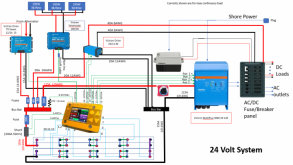
Thinking this through, the polarized breaker may still work. Take a look at this design that is being built right now.

1606940070474.png

Assume the fuse next to the shunt is a directional breaker with the positive closer to the battery. The size of the fuse is determined by the total load. (the DC-DC converter and the Multiplus). The three chargers (Orion Smart, Smart Solar and Multiplus) combined will not create a current anywhere near large enough to blow the fuse or a breaker of that size, so you can't count on it do do anything for you. However, this is not a concern for a couple reasons. 1) They each have their own smaller fuses and 2) the output current on each of these devices have built in limiters.

Having said all that..... I would still use a fuse.
 
Correction.... Since the current in the 'backward' direction would be low, it would never trip the breaker anyway.
If I used the polarized breakers backwards, I might have an 8A Isc PV panel, 145Voc on a cold day, going through a 15A 150V breaker. That will never trip. If I closed the breaker and there was a short circuit, while it wouldn't trip, I would later open it and the contacts would be expected to interrupt the current. Not confident it would do so successfully with "wrong" direction of current. (50% of current rating, 95% of voltage rating.)

Turning off the array when feeding the SCC, would be carrying Imp and upon opening it would rise from Vmp to Voc. Assuming SCC doesn't draw down voltage on its capacitors in less than 50ms, maybe 15V across the breaker so I expect it to work under no-fault conditions if wired backwards.

My preferred solution is to mechanically gang all polarized breakers feeding a single MPPT input, and connect them forward. The backward one trips in case of a fault, and the forward ones interrupt the current.
I happen to have a 6-gang 15A 100V polarized breaker from Outback. It was meant for a 600Voc string but I'm going to repurpose it for 6 parallel lower voltage strings.
 
Thinking this through, the polarized breaker may still work. Take a look at this design that is being built right now.


Assume the fuse next to the shunt is a directional breaker with the positive closer to the battery. The size of the fuse is determined by the total load. (the DC-DC converter and the Multiplus). The three chargers (Orion Smart, Smart Solar and Multiplus) combined will not create a current anywhere near large enough to blow the fuse or a breaker of that size, so you can't count on it do do anything for you. However, this is not a concern for a couple reasons. 1) They each have their own smaller fuses and 2) the output current on each of these devices have built in limiters.

Having said all that..... I would still use a fuse.

I would rather have non-polarized breakers anywhere current flow is bidirectional.
It has to be able to trip and interrupt if battery feeds into a short.
If manually used as a disconnect, or if excessive charge controller connected, it should be able to interrupt in the other direction as well.
So long as battery voltage holds up they may never see a large voltage across them in that direction. But trying not to rely on SCC voltage regulation or characteristics of a fault.
Busbar gets shorted? Battery fuse/breaker opens. Charge controller breaker should also be able to interrupt current, if charge controller decides to keep trying with that it thinks is a completely dead battery.
Fuses are good, but they don't blow without overload so they don't protect switch or breaker being opened. (only extreme overload, where fuse and breaker are in a race with each other.)

Three PV panels in parallel in that drawing. Fuses are lacking.
 
Yes, fusing on PV arrays gets weird. For serial only arrays, they can handle a short circuit without damage so a fuse or breaker is kinda useless as a safety device.... but the breaker *could* be used as a switch.

Where current protection comes into play is on Parallel panels or strings of pannels. If you have a short in/on one panel, you don't want the combined current from all the parallel panels (or strings) dumping through it. Consequently, if you have a directional current protection device, it needs to trip if current is going backwards through the panel.

In general, I don't like using breakers as switches.... for the very reasons you describe above. If I feel I need a PV disconnect switch, I would put in a switch (In addition to any breakers that are needed.
 
A newbie here and working on my system design. I am considering using the Square D QO load center for my battery distribution. I am looking at purchasing twelve 2.1Kwh, 180Ah, 12V Carbon AGM batteries (50% DOD). Plan to have 3 48V strings. Putting this on a Sol-Ark 12K. Understanding that the Sol-ark 12K charge controller has 185A capacity; 185A / 3 48V batty strings = 62A I was thinking maybe 70A breakers for each string of 4 batteries.

Would this load center support this configuration?

What size wiring for each of the strings to the 70A breakers? It seems that most of the battery cabling is usually 1/0 or better going to the bus bar. Not sure 1/0 would fit in those 70A breakers. I appreciate your advice, ideas and direction.
 
The 70 amp QO breakers are rated to interrupt up to 10kA short circuit current, which should be sufficient for AGM.
The largest wire that will fit is 2 awg.
2 pole breakers would work with 48V battery, according to the voltages Square D supports. Single pole, would exceed UL voltage listing.


Wires 2 awg from each battery string to breaker, and larger cables from busbar to inverter.
Up to 100A, QO panels use aluminum bus. 125A and 225A are copper.

Having four 70A breakers would exceed 225A rating. How about four 50A? Although, 200A isn't much headroom above 185A draw.
I think these would meet current handling (if limited to 225A total) and voltage requirements, but a 225A box is large.

Do you need to switch battery strings?
Alternatives would include Midnight breaker (175A or 250A) for inverter and fuses per battery string.

I just have fuse at battery, because breaker is built in to my inverter.
 
Why are you using 2-pole breakers? That's for 240VAC. Midnite Solar has a disconnecting combiner box designed specifically for combining lithium batteries. Use the right product for the job. You'll need multiple, as they are for 10 batteries, but it's cheaper than the alternative of a fire. https://www.midnitesolar.com/produc...e=Combiners&productCat_ID=9&sortOrder=1&act=p
You aren't with us anymore but I still have to jump on your answer, as you were so wrong. The 2-pole Square D QO breakers are also UL approved for DC. In this case the highest voltage level these breakers will ever see is 61V and the highest amperage is 20AMP. This is a huge cushion from 240V but they are actually rated for 125V DC!
 
Back
Top