diy solar

diy solar

Battery bank : lead acid

Right now my concern is to have 2 10awg wires running 50' thru the house .

Look up 10 awg in the following tables:


10 awg has ampacity of 40A for up to three current-carrying conductors in a cable. However, the (*) refers to a note that says maximum 30A over-current protection.
If you have 4 to 6 current carrying wires (don't count separate ground wire for frames), derate to 80%, 40A x 0.8 = 32A. Still fused for 30A.

When connecting PV panels to a wire, assume that due to unusual illumination (extra light reflecting off clouds) they could produce up to 1.56 times their rating. (Actually, it is assume they produce 1.25 times rating, then add an additional 25% as safety margin.)

30A / 1.56 = 19.2A maximum total Isc of all panel strings connected in parallel.

Within those limits, wires are pretty safe against overheating. It is connectors that usually fail. So keep connectors where they aren't likely to cause a fire, e.g. inside a metal box.

Bad connections, damaged wires, shorting due to rats eating insulation can cause arcing and fires. For this reason, recent codes require AFCI for circuits going to PV panels on the roof (unless low wattage, like 300W total on a microinverter). Your 2000W of PV and 100 Voc is quite enough to make an arc and start a fire. Best if either the panels are ground-mounted or you have AFCI (which is typically built in to some inverters and charge controllers, but may have to be enabled.)
 
Awesome, I was hoping I would come up with a chart for this. I night even understand how to read this. I dont want to involve the city yet but I need to figure out where the codes are for DC running through the house. All my connectors will be in the back yard and imagine they should he waterproof and behind the panels .
I would like to know if they would need to be in conduit running through the basement ceiling or do I have to rough them in and run them through joist. I'm not sure because they aren't 120 volts ac.
Before I get the panels I have to askthis: will these wires demand the same ultimate respect that I give any AC wire I negotiate? Working with 12 volt batteries has changed my habits to lower my guard a little.
As always, thanks for the info and the chart. I have to study it and read up on AFCI.
Have a nice evening.
 
The chart has columns for types of wire, including temperature rating of insulation. Some insulation has a different temperature rating if wet. It assumes up to 30 degree ambient (so 60 degrees C rise to 90 degree max insulation temperature, for instance.) If used somewhere hot like an attic, there is derating to be applied.

Higher voltage DC is dangerous, but 100VDC may or may not be more of a shock/burn hazard than 120VAC. Definitely make sure you don't come in contact with it.
I like switches or touch-safe fuse holders that open both positive and negative at the charge controller, and touch-safe MC4 connectors at the panels. First I open switch to stop current flow. Then I disconnect both ends and double-check with a DMM before working on wires.

I'm not sure if Romex plastic cable is allowed or not. I have everything in metal conduit. You can Google to find applicable parts of the NEC.
 
Good stuff.
I'm likening the metal conduit thru the basement. Temperature does not seem to be a issue.
Supposedly, the outside wire is weather resistant wire. I have to look at it when it arrives I would like to use plastic conduit and run it thru 20' of the back yard.
For now, I have to buckle down and confirm for myself that 3 panels and 10 awg wire are within limits. I dosen't sound lik I need a fuse. I'm sure the controller will have it's own safety.
That chart you sent describes wires like
(14/2 with a ground etc.)
I am using a red and black 10 gauge wires thru a 70°f +- 10°F basement in metal conduit. I will end up with 4 wires. Would it be fine to run them together?
Are you trying to find total Wh or available Wh?
Lol, good question; thanks.
There inlies the question.
Clearly, it makes sense to use "available ah" to calculate available "wh" and load watts .
So , is available wh/ load watts an accurate duration of time?
However, in a charging situation is it logical to say I would be interested in total battery ah,then total wh . Then PV watts would charge the bank in a duration of time?
Total battery bank wh/ PV watts.
 
Look up 10 awg in the following tables:


10 awg has ampacity of 40A for up to three current-carrying conductors in a cable. However, the (*) refers to a note that says maximum 30A over-current protection.
If you have 4 to 6 current carrying wires (don't count separate ground wire for frames), derate to 80%, 40A x 0.8 = 32A. Still fused for 30A.

When connecting PV panels to a wire, assume that due to unusual illumination (extra light reflecting off clouds) they could produce up to 1.56 times their rating. (Actually, it is assume they produce 1.25 times rating, then add an additional 25% as safety margin.)

30A / 1.56 = 19.2A maximum total Isc of all panel strings connected in parallel.

Within those limits, wires are pretty safe against overheating. It is connectors that usually fail. So keep connectors where they aren't likely to cause a fire, e.g. inside a metal box.

Bad connections, damaged wires, shorting due to rats eating insulation can cause arcing and fires. For this reason, recent codes require AFCI for circuits going to PV panels on the roof (unless low wattage, like 300W total on a microinverter). Your 2000W of PV and 100 Voc is quite enough to make an arc and start a fire. Best if either the panels are ground-mounted or you have AFCI (which is typically built in to some inverters and charge controllers, but may have to be enabled.)
Does this make sense?
3@ of my PV panels in series output is 143.4 volts and 27.18 x 25 % =34A I could us a 80' 10awg that is rated for 40 amps at 90°f. NO FUSE untill it reaches a controller or hybrid inverter.

Is it necessary to adjust the voltage output to expect an increase of voltage of 1.25 ?

There are two 1.25 factors we use, both for current not voltage.
Assume PV panel might make 1.25 times its rated Isc (extra light reflecting off clouds)
Size wire and fuses 1.25 times large than that, to avoid nuisance trips, 1.25 x 1.25 = 1.56. (For house wiring, breakers are 1.25 times maximum expected continuous load, eg. 20A breaker for 16A max continuous. But brief surges higher are OK.)

There is an adjustment for voltage as well. With PV panels, when weather gets colder the voltage gets higher. Usually not on the label, but data sheet should give temperature coefficient of Voc. It will be somewhere between 0.2%/degree C and 0.4%/degree C. Label ratings are for 25 degrees C. If the record coldest temperature for your location is -15 degrees C, that's 40 degrees colder than nominal. 40 degrees X 0.4%/degree = 16%. So in my case I would multiply 143.4V x 1.16 = 166V. Note that is too high for a charge controller with 150V max spec, either need 200V controller or only two panels in series.

If you have 3 strings of PV panels in parallel (making 27.18), then each string is supposed to have a fuse, so if it shorts and the other to dump current into the shorted one it is protected. Although with just 3 strings the numbers usually look like the fuse would never blow anyway, and for some panel ratings the math tells me 2 x Isc x 1.56 doesn't even reach the required fuse size so maybe code doesn't require a fuse. More than 3 strings the current does get too high.
Fises are our friend ; and, I will fuse everything
Does 3 strings mean 3 controllers?
Also, the 2 @ 200 amp controllers is the price exstranious?

I have to do the math for the average again. I will show the math asap.is there a way you could help me find the chart for the insulation effect for Missouri?

I will get back to you asap.

I would like to check the math before I condemn the 3s2p wiring.
Thanks.

3 strings doesn't mean 3 charge controllers.
You can connect 3 strings in parallel (that's when fuses are recommended) and connect them to one MPPT input of a charge controller.
You might have a charge controller (or inverter) with multiple MPPT inputs, in which case each string might go to a separate MPPT input.

A 200A controller would be considerably more expensive, but what I'm suggesting is that a 200V controller could be used to handle Voc of a 3s2p array. Midnight offers 150V, 200V, 250V controllers. The higher voltage ones cost more per watt than the lower voltage. I also saw "200V" in description of an Epever charge controller on Santan's site, but based on other models listed not sure if that could be a typo. Better find manufacturer's data sheet to double-check. Probably 2s3p with fuses and a 150V charge controller will be most economical.


"Insulation" is what keeps heat (or electricity) from flowing.
"Insolation" refers to sunlight.
Google helpfully offered me hits with corrected spelling, but left in one matching what I asked for:


I'm not condemning the 3s2p wiring, and I commend you for contemplating before committing to it.
 
It is so close because I come up with 42.2a for 2 strings ;yet , 3 string ; I'm sure, if I do the math it would be wonderful for 10awg. I could run 3 homeruns 10awg and connect 2 panels (110.896 v with the 16% added) I guess I would have to find a good MPPT and keep adding 2 panels at a time.
 
I worked today so I have t give my brain a break; but, one more silly question. Can I run 6@ 10awg wires thru one conduit?
Thanks , have a good evening.
 
42.2a for two strings? What was the math to get 42.2?
That might be current out from an MPPT controller into the lower battery voltage, but would not be current from two strings of PV panels.
I think it could be 9A Isc x 3 strings x 1.56

A good MPPT charge controller will let you over-panel while using 12V battery, and will handle more power if you switch to a higher voltage battery.

I worked today so I have t give my brain a break; but, one more silly question. Can I run 6@ 10awg wires thru one conduit?

Yes, and the NEC table shows the same 80% derating for up to 6 current carrying conductors.
If 90 degree insulation and 30 degree environment, 10 awg will have 40A x 0.8 = 32A ampacity, and is allowed 30A fuse or PV Isc x 1.56

Conduit has to be large enough. Even if you see a table saying that you can fit a given number of wires in a conduit, you may not be able to pull them through. I recommend oversize conduit to make it easier.

No way you should need separate 10 awg runs for each string of PV panels. I think one pair of 10 awg will meet specs for two strings.
Or 8 awg for three strings. I use 12 awg for one string (and I have a lot of strings wired through one conduit, so more derating.)
 
I am not sure how to look at it.; that is, if this math is accurate.
one reason, the array is facing due south with 3 very tall trees ; yes, they very well could be cut down one day and the sunlight will change from just okay exposure to intense.
so, one day the 3s panels may crank out the 27.18amps and if you assume clouds and reflection that may or may not occur when the array is cranking out top performance amps you would account for 1 25 or roughly 7 amps which puts the amperage at 34 amps.
Then, factor in another 7 amps (1.25) that allow a tolerance for nuisance breaker trips ; and, that calculates to be 42.2amps.
. Now, 42.2 Amps exceeds the 40 amp ampacity of a 10awg copper wire in a weather resistant insulator.
. So, if the 7 amps added for nucience is " "fudged" a little to 5 amps then you would see the 40.2 ampacity reached when the 3 panel array are performing at peak performance (which is unlikely) and they are in a sustained over exposure to the reflection.
is this an unsafe assumption?
. Also, on the DC breaker box or the inline fuse topic: I kinda like the breaker approach but, are there in line fuses that can be easily reset?
thanks.
 
Last edited:
"3s" won't produce 27A, it will produce 9A.
"3p" would produce 27A.

Fuses on PV side should never blow. The PV panel doesn't produce enough current to blow them. They only blow if you short out one string of panels while several other strings are paralleled with it, and backfeed it with excessive current.

For battery connection of inverter or charge controller, fuses also should never blow unless there is a short.

The in-line fuses are one-time, piece of metal that blows. So you replace it.

Breakers or fuses go in a box. I have a problem with some breakers sold for that purpose, don't think they can actually work as advertised.
 
Do yo think that the 3p configuration is close enough to go with? And that would have to take into account a 200 volt input MppT that I just researched a little and I think I should redo my math to accommodate 3s2p and get a better price on the appropriate MPPTs because the only 2 200v 40 amp MPPT was around a grand. :(.
 
Is this math correct; also is the 112.896 v DC estimation qualify me to use a hundred volt 30amp Mppt?
Also, is 110.896 v DC considered " low voltage and run safely thru the basement pinned up to floor joists or roughed in without conduit?
Thanks.

2s3p

VOLTS:47.8v×2=95.6v-->95.6v x 16% insulation effect--> 95.6v x 16%= 95.6v+15.296=110.896v

AMPS : 18.12amp x(1.25 insulation ×1 25 nuisance)-->18.12amp x 1.5625 = 28.3125 amps.
 
If the calculations show 113V or 111V you can't use a 100V charge controller, would kill it.
On a 25 degree C day when it put out 96V things would be OK, but on a cold day when voltage goes above 100V the the charge controller would fail.

For 2s you need a 150V controller. If you connect the panels 3s you need a 200V controller.

Two charge controllers - that gets expensive. If you have over 2000W of PV panels and a 12V battery system, charge current approaches 200A so you need two 80A or 100A charge controllers to use it all.
Instead, why don't you just use a single charge controller. Charge current will be clipped at its 80A or 100A rating, but that's still a lot of power.

If you later change to 24V system, that one charge controller will be all the array needs.
You're already playing with > 100VDC PV array, which is a shock hazard. A battery that's about 30V fully charged isn't considered a shock hazard unless maybe you are soaking wet. It is commonly used as starting battery system for some diesel trucks.

Have you bought just PV panels, nothing else so far?
There are hybrid inverters available which connect to strings of PV panels, AC from grid, AC to loads, batteries. Some are batteries optional. Considering the price of charge controllers, you might find a better bargain with a hybrid. Some can be configured so they don't back-feed the grid, just power loads connected to them. Some can have current transformers connected at the main panel so they backfeed the house but don't backfeed the grid.


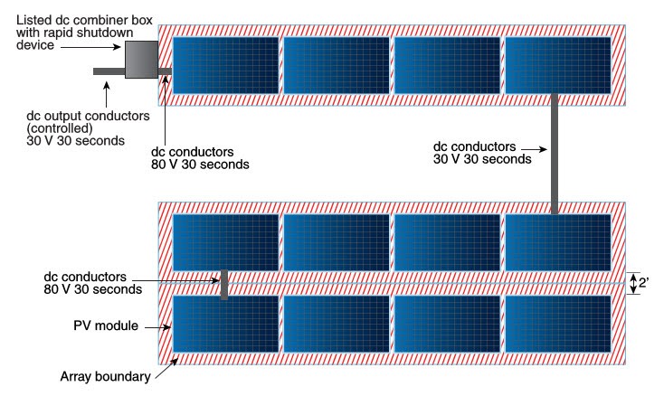
I'm not sure about wires in plastic cable vs. in conduit, but "Rapid Shutdown requirements apparently apply to PV wires that route through the house even if the PV panels are ground mounted, not on the roof. I think you would need a disconnect switch outside the house, so firemen can turn it off. It would have to be rated for the DC voltage and current. Maybe if run in conduit on outside of building, then inside the building no more than 3' before charge controller it would be exempt.

 
Great information: i didn't even consider rapid shutdown! I have learned that this vdc wiring requires all the same requirements and respect of any single phase wiring;yet, it seems that when or if it does fail it will produce dangerous arcs!
I am waiting on the panels and 10awg wire and 2 @ 3 to one y connections ( can I tape one of the connectors up and run 2 panels at a time.
Additionally, I have to price a hybrid that may be the way to go for now ; because, my immediate goal is to maintain the battery bank, run my emergency lights and begin to explore basic refrigeration. And 2 panels seems like an excellent start.
Although, now I have to consider just running one panel at a time.
Thanks
 
Thanks again, Hedges
My panels arrive tomorrow and your input should get me started with basic concepts and saftey.
Clearly, I'll be busy setting up 2 panels at a time.
I can not seem to find the specs or c rate for the vmaxtank 225ah.
Does anyone know a useful link to get the data sheet ?

P.s: whose selling a MPPT or hybrid work with 710 watts pv, 110v ,30 amp ; any recommendation?
Thanks
 
Back
Top