diy solar

diy solar

Battery build 48V 16s LF280K.

NICO_SOLAR

New Member
Joined
Aug 20, 2022
Messages
6
Hello everyone,

I'm Nicola from Italy. I'm making this post to share my personal 48V battery build. Online you can find tons of informations. So many informations that becomes difficult especially for a beginner to choose what to do and what not to do. So here I am, asking you to follow my journey and share your knoledge to help me building the battery. Thank you!


I just received 16 matched LF280K cells from Amy Wan Luyuan. @Steve_S
I also bought:

16pcs grade B battery
1pcs JK BMS JK-B2A24S20P
1pcs TESTER YR 1035+
1pcs EBC-A40L High Current Power Battery Capacity Tester
20pcs INSULATION SHEET
2pcs red black 150A power terminals

The cells looks good, only minor defects, some have slight swelling, all the cells voltages and internal resistance IR were tested.
All the cells were between 3.2931----3.2963 Volts, with an IR of 0.2 and 0.21 mΩ.

a1.jpga2.jpg

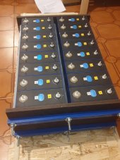
Yesterday i've built a simple compression device. I've barely compressed the cells. I will use the compression device only to keep the cells firm, prevent swelling and bus bars from bending. I will not compress them to the 200kgf.Cm pressure (as the producer recommends) as i have no way to measure the force.

a3.jpg


Now i want to top balance them. To be on the safe side, i will balance them first to 3.55v unattended, then to 3.6V
As the voltage difference between each cell is small 0.003v (smaller than<0.15V recommended) i'll connect them in parallel using the bus bars provided without pre-balance them.

ab.jpgaa.jpgac.png


Any suggestion, advice is always welcome!

Links
This is swollen or normal?

Explanation for Beginners of Top and Bottom Balance

Should I make LiFePO4 Battery Compression?

Luyuan Tech Basic Lifepo4 Guide
 

Attachments

  • a3.jpg
    a3.jpg
    211.8 KB · Views: 26
Last edited:
Cool. I recommend not charging to 3.6V for swollen/used cells. Charge to 3.5V.
https://diysolarforum.com/threads/r...e-for-diy-lifepo4-batteries-sticky-post.5101/

Have you considered an active balancer? It would probably help overcome the runners that are common in used and older cells. The internal resistance of each cell tends to be different in bloated cells (even though they may have been "matched").

Keep up the good work. 48V banks are serious business. Be careful.
 
Hi there.

Everyone get's bent over compression and I've explained it too often to do it again. You did GOOD ! They do not need to be "squeezed" hard, just enough to prevent movement and putting stress on the posts.

The 0.20 & 0.21 resistance is right on the mark and this will really make a difference in them being balanced and at identical voltage, throughout the Working Voltage Range of 3.000-3.400 Even 3 mohms makes a difference that becomes visible.

Top Charging to 3.600-3.650 is fine, this ONLY HAS TO BE DONE ONCE !
Nota Bene: The Acceptable Voltage Range for LFP is 2.500-3.650, this is the Voltage Range these cells CAN work in without damage /harm but is NOT the "Working Range" which s where the Amp Hours actually comes from. Once outside of the Working Range, the cells WILL deviate a bit. It's normal. BE PATIENT it takes time to charge them to 3.650 and be certain to let the Amps Taken drop to <7A for full saturation. As soon as you stop charge, the cells will begin to Settle down this is Normal ! Leave them connected in Parallel for at least 24 hours Post Charging before assembly into a Pack.

Swollen or not: Keep in mind that the Aluminium Casing is about as thick as a soda pop can and they will expand & contract a little bit, that is normal and is subject to Temperatures and other factors. They should be perfectly flat mostly when at 25C temp. note you can squeeze them and they will flex a little, shake them and you'll hear a little bit of slushing sound from the liquids within.

IMPORTANT TIP !
Before attaching the Busbars, wipe down the Cell Terminals (screw threads & nut faces as well) & Busbars with Rubbing Alcohol (99% Pure is best). Pick the shiniest & most unmarked sides of the Busbars and places them face down to make contact with the cells pads.

Last Known Good JK BMS Andriod App is V.4.9.2
Link to it: https://diysolarforum.com/attachments/极空bms_4-9-2-apk.120726/

JKbms Sense Lead Terminals: the wires are 22awg, strip the ends a bit longer (do not cut off the soldered tip of the wire), fold the wires in half and CRIMP the Terminal (no soldering) remember to Shrink Wrap the barrel side. Use a Heat Gun and be careful as you can melt the wire cover if not cautious. After you are done, also wipe them with Alcohol as well.
! * ! check your Sense Lead Wire Resistance with a Good Quality DMM/DVOM before installing !

Recommended JKBMS "Advanced Settings" below. (DO Check each value, the factory defaults are terrible !)
Remember that it will take two full charge/discharge cycles before the BMS' are reading accurately for SOC.
1668722069256-jpeg.120672

You will see this "User Private Data" parameter at the bottom as shown, this is to name the pack internally to the BMS, nothing else. This does NOT change what is displayed in the BMS App, that is changed separately. See the BMS Documentation for those details. LINK HERE: https://github.com/NEEY-electronic/JK/blob/JK-BMS/JKBMS INSTRUCTION.pdf

Hope it helps, Good Luck.
Steve
 
What a great thread to have for us to follow when putting a pack together. I have bookmarked and will use when my 4S 100Ahr grade A cells + JK-BMS arrive from Amy (Luyuan).
A few questions @Steve_S
Why crimping only for the balance wire ring terminals?
I saw that Steve uses a fibre tape of sorts to stabilise cells in packs of four. What is the properties/name of this tape so I can try track down a suitable alternative here in Australia?
Do you recommend a conductive protective paste for the terminals or just cleaning with alcohol?
Thanks.
- Soldering is tricky and if not done right & with the proper solder can (often does) throw off the resistance in the sense leads. Using a good quality SN-06 or SNA-05 (0.5-6mm) hand crimper for O type or Y type non-insulated terminals is best. Remember to put 1cm of quality (with adhesive) shrink wrap on the wire BEFORE crimping LOL !
- Yes I use Fibre Tape, many companies make the stuff, it is just fiberglass reinforced tape. I use CanTape brand or EzTear by DuckBrand.com Again I do NOT heavily squeeze the cells, hand tight snug and then tape. I allow roughly 1mm extra space on all 4 sides inside of the boxes I make to allow for it.
- Always clean with Pure Rubbing Alcohol.
-- there are many coatings / pastes & even liquids, I do not use it but many do, I've found suggesting it cause a pile of twaddle. I should point out that if in a Humid Zone or Marine application it is very wise to use to prevent corrosion potential. Now I know that @upnorthandpersonal has found some of the best stuff going and hopefully, he'll chime in with a response to that. He did extensive testing & evaluation.

In my Signature, "About my System" link, I believe Page 2 has how I assemble my battery packs using 3/4"/19mm Plywood boxes and 10mm Polycarb Clear Tops, there is also an image of the wood with measurements and how it is screwed together using cabinet maker screws in pocket holes. I use a Kreg Jig "R3" to make them which I use for cabinetry & more so it paid for itself many times over.

Hope that answers your questions & helps, Good Luck.
 
Hello guys, thank you for all your suggestions.
I'm back, I'll try to post minimum twice a week, so it can be more interesting to follow.
In the past days I've made few aluminium bus bars, because those provided were not enough to make 16 parallel connections and two copper cables.
At first I wanted to make all of them of aluminum, to have the same resistance, but I was lazy so I made only those I needed. (I hope is ok, otherwise I'll make the others)


In the picture you can see:

(A) 16 mm2 copper cables with high quality terminals
(B) aluminum bus bars
(C) NEGATIVE charging cable
(D) POSITIVE charging cable
(E, F) Voltage sensors cables for the charger.

q2.jpg

Next step is to charge the battery. My charger is programmable, so i can set : C-CV (Charge costant voltage) with cutoff current.
D-CC D-CP (discharge costant current/ costant power) with voltage cutoff.

My idea is :
1) Charge CV 3.5v at max Amperes (35A) , i'll set cut off current <1A
2) Wait one day and test the voltage.
3) Charge them to CV 3.6/ 3.65 v at max Amperes (35A) , i'll set cut off current <1A
4) Wait one day
5) Discharge them to 3.3V (70%) Because i'm still waiting for the inverter.
6) Remove the Busbars and connect them in series, build the wooden box and make the BMS connections.

q3.png
 
My idea is :
1) Charge CV 3.5v at max Amperes (35A) , i'll set cut off current <1A
2) Wait one day and test the voltage.
3) Charge them to CV 3.6/ 3.65 v at max Amperes (35A) , i'll set cut off current <1A
4) Wait one day

1) Charging with 35A I recommend that you set your charger to 3.4V max, a few days ago I charged matched grade A cells with 10A and at the end one was at 3.7 and other at 3.8V.
2) Eve says that you only have to wait 1 hour.
3) Don't charge over 3.5V without BMS.
 
Back
Top