Bud Martin
Solar Wizard
- Joined
- Aug 27, 2020
- Messages
- 4,843
What is the P/N on that diode?
Yes. it runs too hot.


Yes. it runs too hot.
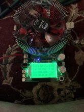
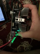
It has two diodes. If you run it at 20 amps, the PCB will discolor and turn brown, same design, same problem. I have 3 different versions, they are all the same basic design. Be careful and don't burn your fingers.Here’s one I purchased on Amazon. Curious to see how it compares. Mine is rated for 20a as well. Haven’t used it yet.
Its the junction temperature that yoiu have to be concerned about, typical max junction tempearture is around 150c, you will have to calculate the size of the heatsink based on thermal resistance of the device spec,, etc., thermal resitance will be shown degree C per Watt.
I also stich Thermal VIAS between top top layer and bottom layer of PCB beside using proper heatsink to manage the thermal issue. The thermal probes also need to be place at the right locations to get more accurate readingI tend to design assuming PCB and air will be at 85C. A power device often has spec 150C maximum junction temperature and I would design to keep its junction no higher than 125C. Cooler of course would be more reliable and might be a target for some systems.
With his thermocouple on bottom PCB, if the plane there isn't electrically connected to the device, may read much lower than case.
Top side where package tab solders to PCB would give a better reading. From there I would calculate junction temperature using power dissipation and theta J-C
I can cool a part quite effectively without a heatsink (like this diode) using FR4 to carry heat from electrically connected copper to ground plane, in the event it doesn't connect to the plane. But to do that I specify layer thicknesses and layout area.
This board could be reworked by desoldering the diode and adding a large piece of thick copper underneath as a heatsink.
Oddly enough, the last diode I replaced (MUR3060PT, not on this tester) has a junction temperature rating of 175 degrees Celsius, and routinely dies after 30 to 60 minutes with the heatsink measuring 45 degrees Celsius. Like I said, it runs too hot. I'm sure it will last a while, how long is the question, anything that will burn your fingers is running too hot. They also like to die as a short (which may or may not ruin your day and cell). Spec sheets and cheap Chinese parts are different things.Its the junction temperature that yoiu have to be concerned about, typical max junction tempearture is around 150c, you will have to calculate the size of the heatsink based on thermal resistance of the device spec,, etc., thermal resitance will be shown degree C per Watt.


Just purchased the EBC-A40L Zketech. Based on what I have seen on off-grid-garage, its the simplest and coolest way to test high capacity cells, as it also can charge the cell before it discharges, and graphs the test on your PC, and can runto 40amps. Andy has done it on his channel multiple times, with no issues.Very interesting!
I've read about the Riden units. What do you think about the switching power supply itself? Not too noisy?
The step down/lcd bit is quite interesting. There is a review on eevblog.
I see you talk about automotive fuse holders I'm not familiar yet with those and see many models online.
Are you referring to this kind?
View attachment 39929
Do you know of a programmable electronic load at the price and features of the ET5410 with a 4 wire system for remote sensing?
If the voltage from the load isn't accurate, how do you handle LVD properly? Do you just offset it by the difference seen betwen it and your multilmeter reading?
I've also seen an interesting youtube review from Adam Walch on youtube about the ZKE Tech EBC-A05+. Have you heard of it?
It features a charger and load in the same enclosure. With a pc software to setup and see results of charge cycle.
Looked like a nice (from my beginner perspective) all-in-on setup.
View attachment 39930
Considering the advices of "Limiting to ~75% of rated power or 8A @ 12V far safer."
This one is the 180W : https://fr.aliexpress.com/item/1005001458325206.html
So if I wanted to test a 272AH 3.2V lifepo4 cell individually, could I still go up to 25A@3.2v as it's less than 75% of 180W?
Very interesting!
I've read about the Riden units. What do you think about the switching power supply itself? Not too noisy?
The step down/lcd bit is quite interesting. There is a review on eevblog.
I see you talk about automotive fuse holders I'm not familiar yet with those and see many models online.
Are you referring to this kind?
View attachment 39929
Do you know of a programmable electronic load at the price and features of the ET5410 with a 4 wire system for remote sensing?
If the voltage from the load isn't accurate, how do you handle LVD properly? Do you just offset it by the difference seen betwen it and your multilmeter reading?
I've also seen an interesting youtube review from Adam Walch on youtube about the ZKE Tech EBC-A05+. Have you heard of it?
It features a charger and load in the same enclosure. With a pc software to setup and see results of charge cycle.
Looked like a nice (from my beginner perspective) all-in-on setup.
View attachment 39930
Considering the advices of "Limiting to ~75% of rated power or 8A @ 12V far safer."
This one is the 180W : https://fr.aliexpress.com/item/1005001458325206.html
So if I wanted to test a 272AH 3.2V lifepo4 cell individually, could I still go up to 25A@3.2v as it's less than 75% of 180W?

 diysolarforum.com
diysolarforum.com
diysolarforum.com