diy solar

diy solar

Battery configuration and Bussbar selection

acolunga07

New Member
Joined
Jul 24, 2022
Messages
40
I’ve gotten almost everything I need for my 4P4S build using EVE304 cells. I haven’t decided between which configuration to put them in. FilterGuy’s post in beginners resources is very helpful. I will likely go with option A or C in the “12V 4P4S Fortune Cell Layouts” (on p17). I am limited in one direction by ~14” (EVE304s are 174 x 72 x 205 mm). So, option C (which I prefer) puts two side by side (13.7” wide) and hopefully* enough room for all thread used for compression (+ ~.375” x 3). This of course is over the rough ~14” I measured but I’m hoping there is some extra margin somewhere I missed. This configuration allows me to use only 4 spread plates (two large enough to cover two cells) and 3 sets of compression mechanism (one on each end and one in the middle). If this doesn’t fit, I’ll be forced to go with configuration A and have to get twice as many spreader plates/compression mechanism. Thoughts/opinions on either of these options?

Either way, I’m still stuck with needing to get some number of “Heavy Duty” bussbars which leads me to several questions:

1) is the color scheme for this configuration (p17) incorrect? All the other ones use purple for heavy duty and green for factory buss bars. This one has green for “oversized” (vs heavy duty?) and blue for factory. The diagram uses purple/green (no blue).

2) How thick are heavy duty buss bars. I know it’s based on ampacity which is based off the conductivity of the material but does someone have a cheat sheet somewhere with recommended thicknesses or areas based on current? I am still trying to decide how much to cap/fuse protect my system for (somewhere between 300-400A). I am powering a Victron MP II 3kW invertor and misc dc loads in my travel trailer and considering cost/availability of certain components. Speaking of which…

3) What are y’all’s thoughts on flexible buss bars? How much expansion/contraction might I expect from my batteries during nominal use (while under 6-12 psi compression)? I’ve heard numbers ranging around .5mm but have no idea if that’s accurate. Assuming it is, wouldn’t that require flexible buss bars? I was thinking of using these. There are options on AliExpress that have current ratings as well. Thoughts opinions?

4) it seems the most popular disconnect is the Blue Seas 6000m but it is only rated for 300A. What would y’all recommend for 350 or 400A?
 
1) is the color scheme for this configuration (p17) incorrect? All the other ones use purple for heavy duty and green for factory buss bars. This one has green for “oversized” (vs heavy duty?) and blue for factory. The diagram uses purple/green (no blue).
That was a mistake in the document. I corrected it. Thanks for letting me know.
2) How thick are heavy duty buss bars. I know it’s based on ampacity which is based off the conductivity of the material but does someone have a cheat sheet somewhere with recommended thicknesses or areas based on current? I am still trying to decide how much to cap/fuse protect my system for (somewhere between 300-400A). I am powering a Victron MP II 3kW invertor and misc dc loads in my travel trailer and considering cost/availability of certain components. Speaking of which…
There are a lot of DC busbar ampacity charts on line. My favorite seems to have been taken down, but here is a different one. https://stormpowercomponents.com/te...es/copper-alloy-c11000-busbar-ampacity-chart/
(Don't wory that it says 60hz AC. The ampacity shown is close enough for what we are doing.

With a 12V inverter, the current can get quite high. Running at rated power, the DC current will be 3000/12=250A. I would shy away from the factory busbars for this much current.

If you make your own, you should either tin plate them or start with plated stock. Copper-on-alluminum is not a great combination.
I buy copper from Online metals here in the US.

Note: The reason I show heavy-duty bus bars in some places is to ensure minimal load difference between the cells. However, I probably make is sound more critical than it really is. The reason to worry about balancing the load is to make sure you don't have one cell reach it's cycle life sooner than the others. I definitely recommend doing what is practical in this area but 1) In a normal solar application, it is more likely calendar life will get the cell before cycle life and 2) I suspect that over time it all evens out. If one cell is taking more of the load, it will get weaker over time, but as it does, the other cells will pick up the slack and start wearing faster.

For fusing, you may want to review this:

3) What are y’all’s thoughts on flexible buss bars? How much expansion/contraction might I expect from my batteries during nominal use (while under 6-12 psi compression)? I’ve heard numbers ranging around .5mm but have no idea if that’s accurate. Assuming it is, wouldn’t that require flexible buss bars? I was thinking of using these. There are options on AliExpress that have current ratings as well. Thoughts opinions?
To tell the truth.... I don't bother with any fancy compression. I just use a couple of plates and 3 or 4 really long hose clamps and cinch them down. With that, the solid busbars seem to be fine. I like the idea of the flexible busbars that are made out of thin sheets, but they always seemed more expensive than they were worth, so I never tried them. I see they have come down in price, but I have not done a build from cells in a long time.

Are you planning to use Fortune Cells with the blue boots and caps? It seems to me that with the boots and caps 1) there is room for a little expansion so there would be little or no post movement. 2) Your busbar options might be rather limited and 3) all the compression would go through the boots and caps so if there is any advantage to compressing, it would not be gained.
 
I am using EVE304 cells.

Per the referenced document, I should design for 3000W/93% eff = 3226W/12V = 269A x 1.25 = 336A. But this doesn’t take into account possible DC loads (refrigerator, slide out, awning, lights, water pump, etc).

I consider it very unlikely that I will be drawing the max 3000 watts while my lifepo4 pack is at the absolute low voltage before being disconnected and trying to run some major DC load but I guess it’s possible? Maybe 400A is a good design point for buss bars?

Per the link posted, I either need 1/4”, 3/16” or 1/8” x 1”, depending on the temperature I want them to run. 1/4” is probably the way to go here?
 
Per the referenced document, I should design for 3000W/93% eff = 3226W/12V = 269A x 1.25 = 336A.
With the fuse multiplier in ther, the 336 is pretty much a max. Strictly speaking the DC loads should be added to that, but like you said, it seems unlikely you will max the inverter and all the DC at the same time.
1/4” is probably the way to go here?
1/4 x 1 would be absolutely sure to work. 3/16 x 1 or even 1/4 x 3/4 would also work. I would be tempted to go with the 3/16 x 1. The chance of that getting hot is pretty low unless you plan on driving the inverter to its max for extended periods.

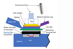
If you go with the welded studs, you might find that 1/4" bars don't work because the stud is not long enough.

The post will have (from bottom to top) Cell pad -> 1/4" bus bar -> Large lug -> Small lug for sense wire -> Washer -> Star washer -> Nut. It is surprising how fast it all adds up.


1684019976135.png

I like to drill and tap a small hole into the busbar to screw the sense/balance wire onto separately from the stud. If you do that it will slightly reduce the stack height on the stud.

If you have the drilled & tapped cells, you can buy an extra long grub screw to accommodate whatever you need. Also, every time the grub screw threads in and out of the terminal, it damages the threads in the terminal pad. Put them in once with some lock tite and never take them out again.
 
Good point on the stack height and yes I do have welded studs. Shouldn’t I put the sense wire on one of the other cells since I am doing a 4P4S build? Each parallel set should be at the same voltage. That way I don’t have to drill/tap the bus bar either. And yeah, shortly after posting I realized that I can undersize it a little knowing that I’m never at 3kW. If I am, it’s for very short intermittent loads (AC starting, microwave, etc). I’m ok with it getting a little warm for those short high power bursts. Alternative, if I run out of vertical room on the stud, I could go wider.
 
Got a question re my 1st DIY 48v Battery build. I am assembling 16 305 Ah cells. I like the idea of of 16S layout for the JK BMS (2a active / 200 amp version) for BMS ability to show each cell's voltage through charge and discharge cycles. I think connecting all the cells via the same bus bars would be best for accuracy of BMS cell readings. QUESTION: ? ... If I rack 2 x 8s, ... like one battery bank stacked above the other, ... and connect those two stacks via a 1 foot battery cable in the middle; ... would my BMS readings be the same. ... just wondering if anyone considering that same question has some feed back or a story to share. > Likely no big deal, and most likely set up my new battery with all same bus bars without stacking em half on the other half for a thinner profile.
 
Last edited:
I am using EVE304 cells.

Per the referenced document, I should design for 3000W/93% eff = 3226W/12V = 269A x 1.25 = 336A. But this doesn’t take into account possible DC loads (refrigerator, slide out, awning, lights, water pump, etc).

I consider it very unlikely that I will be drawing the max 3000 watts while my lifepo4 pack is at the absolute low voltage before being disconnected and trying to run some major DC load but I guess it’s possible? Maybe 400A is a good design point for buss bars?

Per the link posted, I either need 1/4”, 3/16” or 1/8” x 1”, depending on the temperature I want them to run. 1/4” is probably the way to go here?
IIRC Victron MP II is 3kVA, not 3kW, which means less wattage, hence, less amps.
That is shown on the datasheet at the different temperatures...
 
Back
Top