diy solar

diy solar

Battery fuse blew?

I'm in the camp that thinks the source was a bad connection / Crimp. There's more I would do.

How did you crimp the wires?

I recommend redoing the battery lugs with quality tinned copper, with a good crimp job, and thicker wires. I am not opposed to soldering cables after they are completed, but have not done them since my crimps are so tight the copper metal fuses together. Trojan has a white paper that says the best way to do battery cables is a good crimp and soldering, and they showed an IR picture to prove it.

IMO, you need to upsize those wiring. I say opinion because I have not done the math. Each Battle Born Battery is supposed to surge to 100 amps, so 8 set up 2S4P would get you 200 amps surge before the BMS kicks in. Also, the 1800 watts you mentioned is about the max that a 15 amp plug will provide, and that's from the inverter, the pull from the battery will be more. My 1300 watt microwave is cooking watts, but pulls 188 from the inverter, which pulls about 2000 watts from the batteries to run it. I mention 200 amps. My system which I erred on the side of caution, I went with a 200 amp fuse for 4/0 wire.

The places you circled are all connectors. The easiest way to get data on heat is an IR gun from a Hardware store; I'm not as brave as I used to be so I don't touch bare wires. The hot spots would nor be good. I notice the connectors are copper. I got tinned connectors to avoid corrosion. I don't know if your copper connectrs have corrosion, yet; they look brand new.

For the ANL fuse, they can be rated to take minutes to blow at the amps they are made for, seconds at twice the their rating, and fractions of seconds after that. I think of them as slow burn fuses because of that. Also, if you did use an audio ANL fuse, those are less expensive and don't have the ABYCC primary battery rating that some other more expensive (Blue Sea, Bussman) fuses are rated for primary battery protection.

For your parallel connection, here's another link that shows a better way to do it: http://www.smartgauge.co.uk/batt_con.html
 
Bad crimps? Bad connections? Recheck your crimps by pulling on the lug as hard as you can. A solidly crimped lug isn't going to come off.

How many amps were you pulling through that circuit? I know what we think is being pulled, which is around 83 amps. But what does your shunt say?

Can you provide a link to the common bus bars you are using? Do I see a crack in the base of the positive bus bar?

Nit picking here, but the fuse should be between the battery and the switch, not between the switch and the common bus bar.

If you put just one wire between the battery and the positive bus bar, does that wire also heat up?
Checked all the plugs and connections and they’re fine. As far as the positive bus bar being cracked, I just put red tape around it to indicate that it’s positive. The bus bars are rated at 250 amps.
I have 6.2 kW of solar. Eight panels at 320 W and two strings paralleled. Another eight panels at 370 W and two strings paralleled. The two charge controllers are 250/100 Victron. I have another 100/30 Victron with 600 W.
Thanks for the information on the proper placement of the fuse, I’ll make changes. That could be a problem with the heat too?
Not sure how to read how many amps come through a shunt?
 
I'm in the camp that thinks the source was a bad connection / Crimp. There's more I would do.

How did you crimp the wires?

I recommend redoing the battery lugs with quality tinned copper, with a good crimp job, and thicker wires. I am not opposed to soldering cables after they are completed, but have not done them since my crimps are so tight the copper metal fuses together. Trojan has a white paper that says the best way to do battery cables is a good crimp and soldering, and they showed an IR picture to prove it.

IMO, you need to upsize those wiring. I say opinion because I have not done the math. Each Battle Born Battery is supposed to surge to 100 amps, so 8 set up 2S4P would get you 200 amps surge before the BMS kicks in. Also, the 1800 watts you mentioned is about the max that a 15 amp plug will provide, and that's from the inverter, the pull from the battery will be more. My 1300 watt microwave is cooking watts, but pulls 188 from the inverter, which pulls about 2000 watts from the batteries to run it. I mention 200 amps. My system which I erred on the side of caution, I went with a 200 amp fuse for 4/0 wire.

The places you circled are all connectors. The easiest way to get data on heat is an IR gun from a Hardware store; I'm not as brave as I used to be so I don't touch bare wires. The hot spots would nor be good. I notice the connectors are copper. I got tinned connectors to avoid corrosion. I don't know if your copper connectrs have corrosion, yet; they look brand new.

For the ANL fuse, they can be rated to take minutes to blow at the amps they are made for, seconds at twice the their rating, and fractions of seconds after that. I think of them as slow burn fuses because of that. Also, if you did use an audio ANL fuse, those are less expensive and don't have the ABYCC primary battery rating that some other more expensive (Blue Sea, Bussman) fuses are rated for primary battery protection.

For your parallel connection, here's another link that shows a better way to do it: http://www.smartgauge.co.uk/batt_con.html
Lots of good information here, I’m trying to upgrade all my ANL fuses. I use Will Prowses Crimper, these aren’t coming loose! I use copper lugs.
The bus bars are from blue sea 250 amp. Everything‘s inside so there’s no corrosion issues.
 
Last edited:
Thanks for the information on the proper placement of the fuse, I’ll make changes. That could be a problem with the heat too?
Not sure how to read how many amps come through a shunt?

No, I don't think the placement of the fuse is related to your heat problem. That's why I said it was nit picking. It's not critical to this thread.

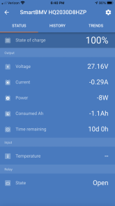
Your shunt should have some way to get the data that it is producing. This is a Victron shunt? If so, the Victron Connect app on your phone or table would have that information.
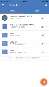
The VictronConnect app has a few things to look at. The first photo shows all my components and the second photo shows the smart BMV-712
 

Attachments

  • 6E06CB85-59E8-4268-BDCA-91CA044FED7C.png
    6E06CB85-59E8-4268-BDCA-91CA044FED7C.png
    267.7 KB · Views: 6
  • 1D362706-1584-46D8-B050-1C6C744479D0.png
    1D362706-1584-46D8-B050-1C6C744479D0.png
    426.4 KB · Views: 6
Watch the current value when you crank up the inverter and heater. There is also a graph that is helpful to look at. Keep in mind that the shunt may not catch any surge amps. I guess it's sampling rate isn't high enough.
 
Watch the current value when you crank up the inverter and heater. There is also a graph that is helpful to look at. Keep in mind that the shunt may not catch any surge amps. I guess it's sampling rate isn't high enough.
OK. I remember watching how many Watts and that’s why I said 1800. Didn’t think about how much current. I really don’t want to push anything until I get all my proper fuses. Hopefully they’ll arrive within a week or so.
I still think the short wires have some issues, as when I turned on the system and the solar panels, those wires in that area it got really warm. It was probably from the panels having stored up energy for the last day and a half. After about a half hour everything cools down again and I haven’t had any issues since.
So something is causing those wires in that area to warm up, so I’m keeping a close eye on them.
Thanks ?
 
Just to clarify, the circles that I drew around the lugs we’re just pointing out that wires are between them and they were getting hot, not the lugs.
 
At what time of day did you run that test, and were all the solar charge controllers online at that time? The reason I ask is that you have the potential for 230 amps of charge coming from the three solar charge controllers. That alone should have satisfied the draw from the inverter and heater. The battery shouldn't have needed to provide any amps if it was a good sunny day.

If your batteries had a low state of charge at the time, then that's a different matter.
You’re right, I would only turn the heater on when I had bright sunlight. And all three charge controllers were on. I’m not sure how you add up all the amps? If I have two 250/100 charge controllers and one 100/30, wouldn’t that give me a potential of 600 Amps. I don’t know if you add all three charge controllers to get this or not. Don’t know enough about it.
 
The second number in the solar charge controller's model is the maximum amps it will output. That's how I got to 230 amps. Of course, that's optimal, max, never likely to happen. But it's still a lot of amps. However, I haven't run the numbers on your panels to see what you're likely to get out of them, probably less than the max the controller can put out.
 
The second number in the solar charge controller's model is the maximum amps it will output. That's how I got to 230 amps. Of course, that's optimal, max, never likely to happen. But it's still a lot of amps. However, I haven't run the numbers on your panels to see what you're likely to get out of them, probably less than the max the controller can put out.
Thanks for that info, this is really been helpful. Here is my list of components.
I have eight Battle Born Batteries wired in series/parallel for 24 V. I’ve been told the capacity would be 400 amp hours in settings in VictronConnect.
I have two Victron charge controllers 250/100
I have one Victron charge controller 100/30
The pin code: 225577 is for the charge controllers.
Victron inverter is 24/3000 Fuse is 300 amps
Victron battery monitor BMV-712 Smart
Go power inverter is 24/1500
Solar panels.
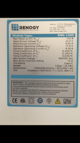
Four 150 W Renogy wired to 24v
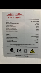
Eight 370 W Santan solar in two strings of 4 panels each. In series configuration and tied in parallel. 25A fuses included.
Eight 320 W Renogy panels wired in series configuration at 24V, these are separated into two strings of four panels and paralleled. 15A Fuses included.
Total is 6.2 kW
Two breakers for the larger charge controllers.
 
Last edited:
Four 150 W Renogy wired to 24v
Eight 370 W Santan solar in two strings of 4 panels each. In series configuration and tied in parallel. 25A fuses included.
Eight 320 W Renogy panels wired in series configuration at 24V, these are separated into two strings of four panels and paralleled. 15A Fuses included.

Assuming optimal (STC) numbers, you're over paneled on the 250/100 controllers. You could get as much as 123 amps and 106 amps, respectively from your panels. The smaller controller would produce a maximum of 25 amps from the panels attached to it. No problem there.

Showing my math so anyone can correct me:

4 x 150 watts / 24v = 25 amps
8 x 370 watts / 24v = 123.3 amps
8 x 320 watts / 24v = 106.6 amps
Total: 255 amps, based on panels alone.
Correcting for maximum controller output: 225 amps

Just because the controllers CAN produce 225 amps, doesn't mean you'll ever see that many amps. It all depends on how much sun you get and the state of charge of the batteries. If the battery bank state of charge is almost full, the number of amps produced by the solar charge controllers will drop way down (unless there is a load, like the heater).

Did you network the solar charge controllers with the BMV? As I recall, this is done through the BMV configuration screen, not the solar charge controller screen.

It is interesting that you're seeing heat only on the positive leg. If it was on both the negative and positive legs I think we might troubleshoot in a different direction. Because it's only on that leg, that's why we're thinking there could be a connection problem there. Given that you may have more watts coming in from the PV than is needed by the load (heat and inverter), it's likely that the batteries are getting charged. This should be represented in the BMV app as positive amps.

Another thing to test is to turn off the solar charge controllers (so no charge amps) and then fire up the heater/inverter. All power for the load has to come from the battery bank for this. If the positive leg stays cool then it would seem there is a problem with charging. But I bet you can charge the battery bank all day long from PV and the wires don't heat up. So I'm not sure if this would prove anything or not.

Grab your voltmeter and check voltages at these points:
1. Where the cables from the switch and shunt meet up at the battery
2. At the switch and shunt
3. At the common bus bars, checking all the studs
4. At the inverter
I hope you understand that the panels were tied into strings, this is to lower the amps. So there is four strings, two to each solar charge controller.
I ran this by the guy who sold me the panels and he said this would be fine. I hope he was right?
Yes I did Network the charge controllers to the BMV.
All the connections are very secure, and like I said before the only time those wires heated up is when I turned on the system. I still believe the panels had quite a bit a charge stored up in them from not charging the batteries for a couple of days. After a while everything (wires) went cold again.
Looks like I’ll have to do more testing. Thanks for all your input! ?
 
I hope you understand that the panels were tied into strings, this is to lower the amps. So there is four strings, two to each solar charge controller.
I ran this by the guy who sold me the panels and he said this would be fine. I hope he was right?

With the calculations in my prior post, we're establishing the maximum number of amps that can come out of the solar charge controller based on the rated wattage of the panels. It has nothing to do with the number of amps going into the solar charge controller.

You can rearrange the panels in whatever configuration you want. 2p4s, 4s2p, 8s, 8p, whatever. It's all the same number of watts.
I’ve been told by others that it only matters about the volts, not the watts. The watts can be over the maximum, but the volts cannot be. In other words it’s the volts that will destroy the charge controller. ?
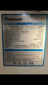
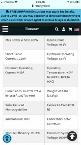
Looks like I may have made a mistake. These are the solar panel information.
four of the 150 W panels
{Four 300 W panels} The 300 & 320 panels may lower the watts to 300.
{Four 320 W panels}
Eight 370 W panels
 

Attachments

  • A2A17F90-3E66-4CC2-B681-282F3F7A1F30.png
    A2A17F90-3E66-4CC2-B681-282F3F7A1F30.png
    480.4 KB · Views: 0
  • A534870A-C9CD-457B-8BB9-B0D14B3E10B7.png
    A534870A-C9CD-457B-8BB9-B0D14B3E10B7.png
    566.1 KB · Views: 0
  • 7F6553C1-B8EA-4E44-9C96-04DEFA7058AD.png
    7F6553C1-B8EA-4E44-9C96-04DEFA7058AD.png
    561.2 KB · Views: 0
  • 7563A3FF-0DD9-432D-8789-9B85EC9A058A.png
    7563A3FF-0DD9-432D-8789-9B85EC9A058A.png
    244.2 KB · Views: 0
Last edited:
I’ve been told by others that it only matters about the volts, not the watts. The watts can be over the maximum, but the volts cannot be. In other words it’s the volts that will destroy the charge controller. ?
Looks like I may have made a mistake. These are the solar panel information.
four of the 150 W panels
{Four 300 W panels} The 300 & 320 panels may lower the watts to 300.
{Four 320 W panels}
Eight 370 W panels

I'm not telling you that there is a problem. I'm telling you that you may not get as much energy out of your panels and controllers as you might think.

Over Paneling involves an array with more watts than the controller's specifications call for. That's not uncommon and is considered acceptable. An array that produces more volts than the controller accepts is bad and could kill the controller.

None of this is critical to your fuse problem. Probably.
 
Again thanks for your input, I keep learning as I go along. I’ve always been fascinated by electricity since finding out about Nikola Tesla! ?
 
Back
Top