diy solar

diy solar

Battery Monitor

Heymirth

New Member
Joined
Sep 8, 2020
Messages
16
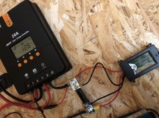
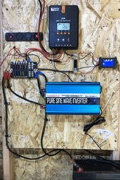
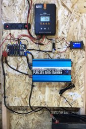
I am new to solar and created a small system for a off grid Shed. I added a battery monitor to measure everything. I wired it in and everything seems correct per Wills Videos but my monitor must be incorrect since I am not getting all the reading. Wiring the battery monitor into the shunt and to the fuse block is confusing and the sticker on my monitor is upside down- so it was confusing to me.
please keep your answers as BASIC as possible. I’m not very smart.

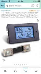
Can anyone help me understand why. I will post which one I bought and how it is wired.
 

Attachments

  • FA3D15FF-FD89-4CAB-B772-FC97260FB1E9.jpg
    FA3D15FF-FD89-4CAB-B772-FC97260FB1E9.jpg
    18.6 KB · Views: 15
  • 08400EDC-7046-44B3-B547-63DC8BFA5EB0.jpeg
    08400EDC-7046-44B3-B547-63DC8BFA5EB0.jpeg
    346.9 KB · Views: 13
  • 4D770FB2-BC0B-43B1-B203-B4C720F50CB5.jpeg
    4D770FB2-BC0B-43B1-B203-B4C720F50CB5.jpeg
    44.6 KB · Views: 16
please keep your answers as BASIC as possible. I’m not very smart.
That makes two of us, however after a long working life in electrical stuff and reading lots I have picked up a hints.

The device you have uses a shunt to measure current, as current flows through the shunt a small voltage is developed that the unit uses to calculate amps and power.
This shunt needs to be fitted between the battery negative and every other negative connection in the system. The unit however is not bi directional and will only measure current, and thus power, flowing in one direction. So it could measure amps and power into the battery or out from the battery.
Fitting a unit like the AiLi would overcome this limitation.

The shunt used for this unit, use the 350A shunt, is termed 'sampler' in the diagram. A good description of the shunt because it takes samples on the current and voltage, carries out some computing and puts the results on the display.


AiLi Monitor.jpg
Mike
 
Last edited:
Your pictures are too dang small (some of them) for me to get a good look at your system. It would help if you provided a link to the exact monitor you're using.

mikeFitz summed it up well when he said the shunt has to be between the battery and everything else. Based on the limited view I have of your system, it doesn't look like you did that. It's only between the solar charge controller and everything else.

Take a look at the diagram I linked to below. I know it's overkill for your situation, but it provides an excellent baseline for how things are wired up.


Attachments

  • 0187ECCC-5408-4092-AD2D-599AE2D063E3.jpeg
    0187ECCC-5408-4092-AD2D-599AE2D063E3.jpeg
    1,017.2 KB · Views: 16
Yep, the shunt isn't wired right. It needs to be between the battery and your inverter.

I'm not a fan of daisy chaining off of the inverter. Will did it in a couple of his boards, but I consider that to be a shortcut used for a video and not something you would want in a production system. A pair of 250 amp common bus bars would simplify your wiring and eliminate the daisy chaining.
Can you explain this better or make a quick diagram on how or what I have to do to fix this? Please. Thanks for your help. I need to take a class on this. But it’s not like they have solar 101 a the community college.
Thanks for your help
 
Battery (positive) -> Fuse or Circuit Breaker -> Switch -> Positive Common Bus Bar
Battery (negative) -> BMS -> Shunt -> Negative Common Bus Bar

The switch is optional if you have a circuit breaker. Most circuit breakers aren't good enough to use in this position. That's way we recommend a Class T fuse.

Once you have that, everything connects to the common bus bars.

This is what I mean by a common bus bar:

 
Back
Top