diy solar

diy solar

Battery not balancing well.

Sunnytheskoolie

New Member
Joined
Feb 12, 2021
Messages
54
Hi,

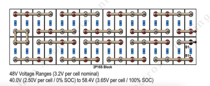
I'm not sure what is going on with my battery/BMS. I have a 32 cell pack, EVE 3.2 280ah, with a REC Q1 BMS.

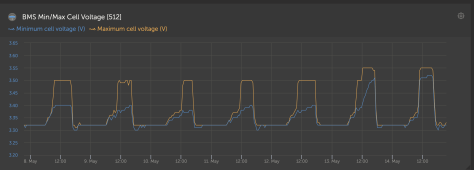
When the battery is drained past about 60% SOC the next day as the pack is charged back up everything is great, the cells charge at an even rate and the BMS doesn't need to work at balancing the pack. If the pack is discharged to anything above about 60% SOC the cells have large voltage differences and the BMS heats up and cools down to balance the pack. You can see in the photo that I only had this happen once in the last 30 days, every other day the BMS had to work to balance those cells.

Any suggestions on what I should start with?Screen Shot 2022-04-04 at 11.38.19 PM.pngScreen Shot 2022-04-04 at 11.38.29 PM.png
 
What are your balance trigger settings on the BMS? I'd first rule out balancing at too low an SoC and throwing off the balance you had, then working to fix it on charge. Second, are you sure the pack fully charged that day the voltages didn't diverge?
 
48V?
2P16S or 16S2P?

Did you top balance?
How many charge amps?

Happen to have a battery wiring pic?
48V
2p16S

I put them all into parallel when I first got the cells and left it like that for about a week. All cells came out to the same voltage before putting them into the pack. I did not bottom balance the cells. When I purchased them they said they were class a EVE 3.2V280AH cells.

What do you mean how many charge amps? I have 3600w of solar on the roof, 9 (3s3p) 400w panels. I have a Victron mppt 150/100 - Tr.

Attached is the wiring diagram and the settings for the BMS at the moment. You can see in the temp section the BMS is at 50C, the cells are balancing and the BMS is getting hot. It does this because the cells charge at such different voltages.

Thanks for the help and really sorry for the delay, I have been traveling in Mexico and didn't get the info compiled sooner.
 

Attachments

  • Screen Shot 2022-05-12 at 5.15.22 PM.png
    Screen Shot 2022-05-12 at 5.15.22 PM.png
    207.5 KB · Views: 16
  • Screen Shot 2022-05-12 at 5.15.58 PM.png
    Screen Shot 2022-05-12 at 5.15.58 PM.png
    162.6 KB · Views: 14
  • Screen Shot 2022-05-12 at 5.20.06 PM.png
    Screen Shot 2022-05-12 at 5.20.06 PM.png
    122 KB · Views: 14
  • Screen Shot 2022-05-12 at 5.20.37 PM.png
    Screen Shot 2022-05-12 at 5.20.37 PM.png
    29.8 KB · Views: 14
  • Screen Shot 2022-05-12 at 5.44.50 PM.png
    Screen Shot 2022-05-12 at 5.44.50 PM.png
    789.3 KB · Views: 17
  • Screen Shot 2022-05-12 at 5.15.05 PM.png
    Screen Shot 2022-05-12 at 5.15.05 PM.png
    243.5 KB · Views: 19
What are your balance trigger settings on the BMS? I'd first rule out balancing at too low an SoC and throwing off the balance you had, then working to fix it on charge. Second, are you sure the pack fully charged that day the voltages didn't diverge?
I am sure the pack fully charged that day. It fully charges every day there is sun.

What do you recommend about the balancing at a low SoC. I attached the settings of the BMS to my previous reply. Do you think that is too low>

Thanks and sorry for the delay getting back to you.
 
48V
2p16S

I put them all into parallel when I first got the cells and left it like that for about a week. All cells came out to the same voltage before putting them into the pack.
You didn't indicate if you actually put a charge on this paralleled bank. Merely paralleling them together to "self balance" and seeing the same static voltage on each doesn't indicate balance.

Well, there is a way - because the differences in voltage between each cell that push current can be near-microsocopic, it can take TWO MONTHS to do so, not a week. Your off the shelf ammeter doesn't go this low to see it happening.

Each cell would have to be charged to full individually, then paralleled, then you take a 2 month vacation.

Oft-forgotten is that a *true balance* can only be indicated while under charge. Just sitting in a static condition can lead to false conclusions.
Ok, so that sucks. I did just let them sit without a charge. When I did that I didn't have any way of charging them because I was at an off-grid cabin with a very small solar system and my bus conversion solar system was not set up.

What do you recommend that I do from here on?
 
First, it looks like you have the BMS set to stop balancing at 3.4V. I think you want it to keep balancing to your top cell voltage, 3.6V.

I put them all into parallel when I first got the cells and left it like that for about a week. All cells came out to the same voltage before putting them into the pack. I did not bottom balance the cells.
I would perform a top balance if possible (it is a LOT of work to disassemble and reassemble, sorry).

Do you have the ability to see which 2P pairs charge the highest and which remain the lowest? I would label your cells and make note of where the pairs rank in terms of combined capacity. This may help you make all of the pairs the same combine capacity later.

Otherwise:
if you do not have time to do a full blown breakdown and want to tinker with hopes of making the pairs more equal in capacity, i'd try the following:
Identify the pair that charges the highest/quickest. This is the lowest capacity pair. If you have a couple that hit the top at about the same time, keep track of those pairs too.
Identify the pair that charges the lowest/slowest. This is the highest capacity pair. Again, make note if there are other pairs that behave similarly.

Assuming that your strongest pair(s) have 2 good cells and your weakest pair(s) have 2 poor cells, i would swap one cell from the strongest pair with one cell from the weakest. If you have others, second strongest and second weakest pair, swap one cell from each pair.

This "should" even the capacity between the pairs. It might take a couple iterations to get your battery to behave enough to charge high enough (13.8V to 14V ??) without your BMS disconnecting.

Let me know if this is not clear (or if anybody has better options!) please ask. I spent a considerable amount of time ranking cells without true capacity testing. Labeled cells (i prefer A, B, C... because the cell positions are numbers) and good notes are vital to making good decisions.
 
Last edited:
I think you might do better to get a charger, or other steady-state source to do this initial balance, rather than rely on variable solar at first.

Also, I see the REC bms uses near 1A passive bleeder resistor (0.9A per spec sheet), but I am SERIOUSLY concerned that your bleeder voltages and some other settings in your BMS are either wrong (bleeder voltages too low near the start of the end peak, rather than near the middle like 3.5 / 3.55v - ie, too low and your resistors will never stop bleeding)

Perhaps pose this question over in the BMS sub-thread to get more expert assistance on the REQ Q1, and if those values are part of the problem. As a non-owner, I won't guess, but my first "sense" seeing those values is that it could be set better.
 
First, it looks like you have the BMS set to stop balancing at 3.4V. I think you want it to keep balancing to your top cell voltage, 3.6V.


I would perform a top balance if possible (it is a LOT of work to disassemble and reassemble, sorry).

Do you have the ability to see which 2P pairs charge the highest and which remain the lowest? I would label your cells and make note of where the pairs rank in terms of combined capacity. This may help you make all of the pairs the same combine capacity later.

Otherwise:
if you do not have time to do a full blown breakdown and want to tinker with hopes of making the pairs more equal in capacity, i'd try the following:
Identify the pair that charges the highest/quickest. This is the lowest capacity pair. If you have a couple that hit the top at about the same time, keep track of those pairs too.
Identify the pair that charges the lowest/slowest. This is the highest capacity pair. Again, make note if there are other pairs that behave similarly.

Assuming that your strongest pair(s) have 2 good cells and your weakest pair(s) have 2 poor cells, i would swap one cell from the strongest pair with one cell from the weakest. If you have others, second strongest and second weakest pair, swap one cell from each pair.

This "should" even the capacity between the pairs. It might take a couple iterations to get your battery to behave enough to charge high enough (13.8V to 14V ??) without your BMS disconnecting.

Let me know if this is not clear (or if anybody has better options!) please ask. I spent a considerable amount of time ranking cells without true capacity testing. Labeled cells (i prefer A, B, C... because the cell positions are numbers) and good notes are vital to making good decisions.
Thank you.

I have finally got a log going so that I am able to track the cells charge speeds. So once I have a week or two of data I will check to see if it is the same cells every time. I'll let you know.

Once I have that data I will be able to swap cells to make the pack better.
 
I think you might do better to get a charger, or other steady-state source to do this initial balance, rather than rely on variable solar at first.
Ok, I will look for one. I am currently in Mexico so I will have to find one at a big city.
Also, I see the REC bms uses near 1A passive bleeder resistor (0.9A per spec sheet), but I am SERIOUSLY concerned that your bleeder voltages and some other settings in your BMS are either wrong (bleeder voltages too low near the start of the end peak, rather than near the middle like 3.5 / 3.55v - ie, too low and your resistors will never stop bleeding)
Can you please explain this a bit more, I don't completely understand what you mean.

Thanks
 
Does your BMS have control over your charge controller? If not that is the first thing to get sorted.

I have my REC set to start balancing at 3.40, and finish balancing at 3.45

Your cells should come into balance in the middle of your balancing range (ie for me at 3.425V)

If you have balancing activated too far outside this range, your BMS will be balancing cells at a different voltage that will then need to be rebalanced as they approach the higher range.

That’s another reason it’s pointless top balancing to 3.65V. Your balancing will need to adjust this to 3.425V when you start cycling the pack
 
Does your BMS have control over your charge controller? If not that is the first thing to get sorted.
What do you mean have control over the charge controller? I have a Victron Mppt and I belive it is set up to talk to the BMS or vise versa
I have my REC set to start balancing at 3.40, and finish balancing at 3.45
I changed my balancing today to start at 3.40 not 3.3 like I had it set to. I shut off the balancing at 3.5

I'm going to test this setting for a couple of days and see how it goes. I'll get back to this thread once I have more data.

Thanks
 
What do you mean have control over the charge controller? I have a Victron Mppt and I belive it is set up to talk to the BMS or vise versa

If your REC has communication with the Victron it will reduce charge current when the first cell reaches its balancing voltage. Check that this is happening.

If the cells are very imbalanced, the REC will reach 55°C, and the charging will pause. If the REC cannot control the charge current the balancing is a lot less effective.

I have installed a REC on a second hand set of cells that were very imbalanced, it took a few months to bring the cells together at the top SOC.

As long as your system is reducing charge current when balancing it will be fine.
 
Update

After changing the balancing start and end voltages from 3.3 to 3.4 and from 3.5 to 3.55 the balancing is looking a lot better. The BMS didn't heat up to 55c either.

I have one cell that is still low though. Any suggestions or just wait and see how it goes for a couple of weeks.

I changed the settings halfway through the day yesterday as you can see by the darker graph
 

Attachments

  • Screen Shot 2022-05-14 at 10.28.53 PM.png
    Screen Shot 2022-05-14 at 10.28.53 PM.png
    185.8 KB · Views: 7
  • Screen Shot 2022-05-14 at 10.29.55 PM.png
    Screen Shot 2022-05-14 at 10.29.55 PM.png
    368 KB · Views: 8
If your REC has communication with the Victron it will reduce charge current when the first cell reaches its balancing voltage. Check that this is happening.

If the cells are very imbalanced, the REC will reach 55°C, and the charging will pause. If the REC cannot control the charge current the balancing is a lot less effective.

I have installed a REC on a second hand set of cells that were very imbalanced, it took a few months to bring the cells together at the top SOC.

As long as your system is reducing charge current when balancing it will be fine.

This depends on the firmware version (now at least). REC made some significant changes, IMO, to their charging algorithm in version 2.7 and 2.8. From the latest manual for the REC Q/Victron Compatible BMS:

When the highest cell reaches the End of charge CHAR voltage setting, charging current starts to ramp down to 1.1 A x Number of Inverter/Charger Devices SISN until the last cell rises near the End of Charge Voltage CHAR (CC/CV). At that point the Maximum charging voltage allowed is set to Number of cells x (End of Charge Voltage per cell CHAR– Maximum Cell Float Voltage Coefficient CFVC x End of charge hysteresis per cell). End of Charge SOC hysteresis SOCH and End of charge cell voltage hysteresis CHIS is set to prevent unwanted switching. SOC is calibrated to 100 % and Power LED lights ON 100 % Charge optocoupler is turned off. Maximum allowed charging current is set to 50% to allow supplying DC loads from charging devices like MPPTs. Charging current is limited to 30 % of the maximum charging current, but more than 5 A near both ends of temperature (Max cell temperature TMAX and Min temperature for charging TMIN) and when the battery is empty (Max discharging current is set to zero).

What can mean in practice (for me at least) is that you will get hard cutoffs depending on your chosen parameters. I have my CHAR set to 3.58, my BMIN to 3.45, and MAXC (cutoff) to 3.65. When charging at about .1C or higher, the ramp down in charge current limit does not occur fast enough to prevent tripping the system at MAXC. This trip occurs prior to a reset to 100%, so the system can cycle between BULK charging and hard cutoffs over and over. No Bueno.

I'm still trying to figure out what to do about this: Raise MAXC to give more margin to cutoff (and allow cells to be driven higher than I'm comfortable), or lower CHAR to give more margin to cutoff (and give up a little on some capacity). Either way means way less opportunity for cells to balance.

Not trying to hijack this thread, but want REC users to be aware of these changes.
 
Back
Top