There is a few of points to KNOW with LFP cells.
1) You "never" want to bottom out the screw in the hole. You could go through the top or damage the cell.
2) The screw is NOT the current carrier. It is the top surface of the "post" and connection to busbar. Typical post is 20mm wide. (varies by manufacturer)
3) Full surface contact between the Bus Bar and Post top is essential. A light coating of No-Ox / Ox-Guard between the post & bar is prudent. Most especially in a Marine environment but any mobile application or if in a damp area. Generally just a good idea period.
** NOTE, best to wipe off the terminal tops with rubbing alcohol so there are no machine oil residues left BEFORE no-ox applied & bus bars attached.
4) Tighten your screw and BY HAND spin it down as tight as you can, then back it off 1.5 turns (preventing bottoming screw). If you need to use a washer (use stainless, NOT Galvanised or zinc coated)
5) NEVER over tighten the screws, stripping these holes is nasty !
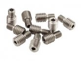
6) DO NOT USE SAE SCREWS !!! These are Metric ONLY !
7) If you need to buy screws, use Stainless ! or Copper/Brass. NO Zinc or Galvanised !
8) If you need to make bus bars, best to use 110 Copper Bar Stock, drill slightly slotted holes (matched to bolt size) so there is little back & forth movement. (pipe bashing is, well a BODGE JOB )
9) IF you have a mobile installation subject to vibration & movement, the use of a "little bit" of Loc-Tite Blue is fine just don't goop it a tiny dab will do. Alternatively, a lock washer or serrated type washer can be used. BTW: a dab of nail polish works just as well and is cheap BUT not accepted by electrical wizards... <<grins>>
The screws for the bus bars rare not intended or designed to handle stresses. Ensure than when you assemble your pack that everything is snug and that the pack itself is bound together with either strapping, 2-way tape so none of the cells can move independently or twist, they should be assembled so the pack of cells is essentially "one solid block". That will prevent any vibration issues, potential twisting when being handled.
The Devil is ALWAYS in the Details !
Hope that helps
Steve