diy solar

diy solar

Battery voltage drop and internal resistance issues

coolbz

New Member
Joined
Jul 25, 2021
Messages
88
Hi everyone, I’m wondering what is the reasonable range of Lifepo4 battery internal resistance.

I ask because my 48v 100ah battery system has been experiencing larger voltage drop when there is larger amps draw.

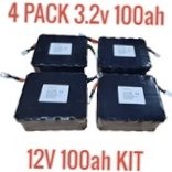
For example, a 20amps draw cause battery voltage drops around 1 volt from 52v to 51v. I measured with volt meter around 0.8v drop is between those 16 cell packs, only 0.2v by bms. I’m using 16 3.2v 32700 cells package from Batteryhookup. So my battery system has 50 mohms internal resistance.

If I try full load of 100amps, the voltage drop will be 5 volt, that is tooooo much. Even 1 volt drop has been causing Growatt to switch power mode unnecessarily since most settings are based on voltage. On the other side, I wish Growatt has built in shunt and use battery capacity instead of voltage to decide when to switch with grid.

Does anyone have experience dealing with this type of issues? Any suggestions?
 
Last edited:
Show us your connections of the cell packs, some proper prep can do wonders of those crimped connectors provided by battery hookup.

Also I wonder why battery hook up pulled the product.
 
Last edited:
Does anyone have experience dealing with this type of issues? Any suggestions?
Yes I experienced that with some used Nissan Leaf modules. Could it be your battery is getting old or has lost capacity?. Have you tested the capacity under different loads. Is it is a previously owned battery?
 
Show us your connections of the cell packs, some proper prep can do wonders of those crimped connectors provided by battery hookup.

Also I wonder why battery hook up pulled the product.

I connected all 16 packs in series without adding anything in between, not even a busbar, then there is BMS, and then 4awg wire to AIO. I didn't alter any connectors. Do you know what prep can help of these battery's crimped connectors?
 
Yes I experienced that with some used Nissan Leaf modules. Could it be your battery is getting old or has lost capacity?. Have you tested the capacity under different loads. Is it is a previously owned battery?
Thanks for asking! No, my battery were brand new and used for only half year on a daily charge/discharge frequency. This issue seem to be there always, so not likely due to drop of capacity, which is good. Capacity wise, it is around 5kwh in total. Although I noticed one of the pack is slightly lower capacity, so it is always the first to deplete and full during a cycle.
 
Also I wonder why battery hook up pulled the product.

This worries me since I don't have any backup battery pack in case part of my battery fail in the future. Maybe they just sold out and will have more from boat?
 
The only thing I can suggest is redo the connections. That should only be a 20 Amp load if my assumptions are correct.
No, this battery pack is rated for 100amps so my 16s system should have 100amps max capacity on paper. From BMS real time data, I have been trying to tell if there is any cell that sags more than others. If that happen, it means that connection is worst than others, correct? But so far I haven't seen any.
 
No, this battery pack is rated for 100amps
I understand the rating. I was assuming that the 1 kW load you reported was at 50 volts so that is how I calculated that you were pulling 20 Amps. The fact that you are seeing voltage sag at 0.2C should be concerning. I would hate to see what it would look like at 1C.
 
I think it is time for you to show us your setup so we can see how wire them up exactly, especially the 16 packs of batteries.
 
Pull some current out of the pack 1/2C? 1C? and measure the voltage drop across each cell if possible. I think I am about 200uOhms per one 280Ah Eve cell. As a first approximation scale your ESR to (200uOhmsx2.8). How does that compare to the data sheet? to what you calculated with measurement? Measure voltage across each connection? Does the voltage reading make sense?
 
Pull some current out of the pack 1/2C? 1C? and measure the voltage drop across each cell if possible. I think I am about 200uOhms per one 280Ah Eve cell. As a first approximation scale your ESR to (200uOhmsx2.8). How does that compare to the data sheet? to what you calculated with measurement? Measure voltage across each connection? Does the voltage reading make sense?
I plan to test a little more, but I’m ready to accept the high ohms and going to try some interesting improvement when my new battery order arrive.
 
A good LFP 100 AH cell with 20 amps load, after 3 minutes of load current, should have no more than 100 mV drop per cell from rested no load cell voltage. You must make the cell voltage measurements directly on cell terminals to avoid connections loss.

For 48v 16s cells, assuming little bus bar connections loss, that would be 0.1v x 16 = 1.6v total voltage slump.

As important is how each individual cell's voltage slumps relative to other cells for same current going through all the cells. Having similar voltage slump for same current means the cells are well matched. They should be at similar state of charge, but between 45% and 85% state of charge should be fine. Also temp of cells needs to be same and greater than +15 degs C. Below this temp the terminal voltage slump increases rapidly with lower temp.

As cells age their voltage slump with load current will get greater. A new 100 AH cell of that type should have about 50-70 mV slump for 20 amps load current after 3 minutes. When it is said the cell's longevity is based on still having 80% capacity, it is really the voltage slump increase with load current that is the greater issue. At 80% remaining capacity, the terminal voltage slump will likely increase greater than 3x at 0.2 CA load current. The voltage slump will increase even more with greater load current making the cell unusable for moderate load currents.

The cell impedance you measure with a 1 KHz battery impedance tester is mostly internal metal conductor loss and only minorly due to diffusion loss. If you measured 0.20 milliohms on battery impedance meter that would only be 20A x 0.0002 ohms = 2 mV voltage slump. That number would be similar to, but less than, voltage slump immediately (msecs) after load is applied.
 

Attachments

  • Rs and Kinetic voltage drop measurement.pdf
    494.8 KB · Views: 19
What’s hiding under the electrical tape? What’s your float voltage?

Maybe you just found the limitation of this cell set up? Just doesn’t have the capacity it should as it ages, that’s why battery hook up only sells cells now.
 
BTW, regarding to the resistance of the cell based on the calculation. Is the calculation based on Voltage measured at each pack terminals (16 data points) or based on the Voltage measured at the BMS - and the B+ output of the pack with all the connected wires? I read and read but still not clear to me.
 
OP post #1 " Even 1 volt drop has been causing Growatt to switch power mode unnecessarily since most settings are based on voltage."
OP: from other thread regarding to the GroWatt settings:
My settings are like this:
49.6v batt -> grid
54.5v grid -> batt

If it switches to util mode when Voltage drops is only 1 V, that means the battery Voltage must be at low point of around 51V, which is about 20% SOC according to the LiFePo4 chart I have, whIch mean the cell Voltage of around 3.2V. Am I correct?
 
Last edited:
Voltage must be at low point of around 51V, which is about 20% SOC according to the LiFePo4 chart I have, whIch mean the cell Voltage of around 3.2V. Am I correct?
That would be correct if battery is not loaded with any current draw.
 
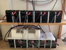
View attachment 81437
Yes, I should have load picture earlier to explain this.
Interesting. Before seeing the picture, I had assumed 1p16s, built from only 16 cells. You have cleverly built a sort of 5p16s battery with 80 cells, using a single 16-port BMS to control the voltage within each "5p" group as if it were a single battery cell. The issue is possibly that some of your 160 battery cell connections aren't great - and, group by group, one or another has somewhat high AVERAGE resistance on the 10-wire "group to group" connections.

Within each group, the average resistance of the individual small cells may or may not be as expected. If one or more of the small cells is somewhow worn out or poorly connected, in comparison to others, then the remaining and more-favored cells (within each group) might be taking on most of the current load. This would have your battery effectively running at much smaller size, with only one or two of the interconnect "bus wires" being used to and from the more favored cells.

I think that your further analysis will unfortunately be complex, requiring that you "dig" down to the level of individual cells and their connection wires.
 
Back
Top